K3PGP.Experimenter's.Corner
![]()
K3PGP.Experimenter's.Corner
![]()
Home Astronomy Construction Laser Moonbounce Software Guest Misc
A Low
Noise PIN diode Laser Receiver !
By John, K3PGP rev1.1
This article will describe a simple low noise PIN diode front end suitable for laser communications. Two schematics are presented, one for nighttime use and one for daylight use. Although it may be possible to add switching to the front end to allow one front end to work for both night and day I decided against this due to the extremely high impedance involved and degradation associated with loading on the PIN diode.
This circuit is quite well behaved and not much attention needs to be paid to layout other than making provisions for completely shielding the circuit. I've had the best success with point to point wiring as the impedance especially around the gate of the MPF-102 is EXTREMELY high. Because of this the circuit must be completely shielded and must be fed from a well filtered power supply.
The only components that may need slight adjustment are R1 and R2. R1 is adjusted for approx. 6 vdc on the drain of the MPF-102 and R2 is adjusted for approx. 6 vdc on the collector of the 2N5088. The exact voltage isn't critical and anything between 5 and 7 volts should be OK unless you are going to be using this receiver with extremely strong signals and you are trying to avoid clipping. Typical values range from 2.7 k to 3.9 k for R1 and 2.2 meg to 5.6 meg for R2. The 2N4124 may require a slightly different bias resistor if you decide to use this device.
NOTE: There is NO gate resistor on the input of the MPF-102! This is intentional! I have found both through experimentation and by looking over data sheets for PIN diodes that the best noise figure can be achieved only when the PIN diode is feeding a load resistance of 100 megohms or higher.
After playing around with various high value resistors from 10 megohms to 1000 megohms it became obvious that the signal to noise ratio became better as higher load resistors were used. However, the surprise came when the circuit was tried with NO gate resistor. The sensitivity was extremely good under these conditions but the circuit worked best only under nighttime conditions. Although it would also work in full sunlight with reduced sensitivity the gain dropped very noticeably.
If your primary use involves daylight operation you might want to experiment with reverse bias on the PIN diode. This will restore the gain but will result in a severe reduction in weak signal capabilities during nighttime operation as the noise floor will come up very noticeably and much of the receive signal will be wasted in the 82 k and 22 meg load resistors. The noise floor increase will NOT be noticeable during daylight operation due to the high noise level produced by the sun. However, it will be a disaster when it comes to any attempts at weak signal DX work during the night.
Reverse bias applied to the PIN diode also increases the bandwidth, something that will be required if you are running high data rates or experimenting with wide bandwidth modes such as video. The PIN diode response is more than adequate with zero bias for 800 Hz MCW and BPSK as well as subcarriers up to approx. 20 kHz or so.
The 82 k resistor may need adjustment depending on the maximum amount of light that will reach the PIN diode and how much bandwidth you need. Smaller values allow full gain in higher light levels and result in more bandwidth but at the sacrifice of noise figure. (The noise floor comes up drastically!) Biasing the PIN diode like this is NOT recommended for nighttime DX operation !!!
Shielding
Because of the very high impedance involved in this circuit it must be completely shielded. I have been building mine inside of tin cans but I've also built them inside of 35 mm film cans so they could be slipped down in the focusing tube of a reflecting telescope. If you are using a plastic 35 mm film can you will have to wrap aluminum foil around it to serve as a shield and connect the foil to ground. You can either make sure some of the foil comes in contact with ground or wrap some of the foil around a piece of bare copper wire for the ground connection and attach the other end of the wire to ground.
NOTE: You can solder to aluminum foil if you provide a barrier so that the atmosphere can't oxidize the joint as you are heating it. Most types of oil will work for this including the common 3 in 1. Place a little bit of oil on the foil and begin heating the foil under the oil with the soldering iron while using a slight circular wiping motion and applying solder. It takes a little practice to make this work but it can be done. There are various fluxes also available for this such as Salmut Flux but it's probably not worth the bother as simply wrapping a copper wire in the foil and grounding it seems to do the job as little or no current should be flowing in this lead. PS - Don't try the soldering technique inside the house if you don't like the smell of burning oil!
Laser
Receiver Built in a 35 mm Film Can Housing!
 |
 |
 |
This is the preamp built on the back of an assembly that fits inside the focusing tube of a reflecting telescope. This assembly is wrapped with aluminum foil for shielding when in use. The foil is automatically grounded when it comes in contact with the aluminum housing around the PIN diode. The foil that is around the electronics has some pieces of scotch tape stuck to the inside surface to prevent it from shorting out any of the circuitry. Light enters the tube on the left of the assembly. This circuit is set up for nighttime operation but works well in daylight with reduced gain as mentioned above.
Laser
Receiver Built in a Tin Can!
 |
 |
 |
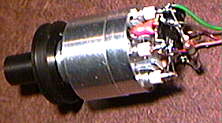
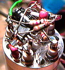
Here's an example of open air tin can construction and is my favorite as it lends itself to quick circuit changes and experimentation with no sacrifice in performance. Although this looks extremely crude this front end has been my best performer!
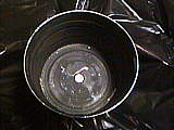
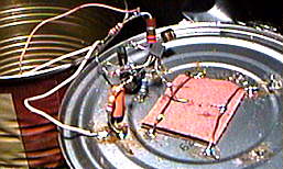
The picture on the left is looking into the 'light' end of the bottom tin can and shows the PIN diode mounted in the center of the can. The inside is painted flat black. The preamp is built directly on the back side of this tin can. The PIN diode is mounted to an insulator and the insulator is held in place with a couple pieces of copper wire. The right photo shows the open air circuit construction. When in use the tin can just to the left is soldered in place over the preamp as a shield.
In the center picture you can see the 1/4 inch audio connector (mounted in the center of the top can) that is used for the output along with a capacitor that is used to filter the 12 vdc supply line. This preamp is normally used with either a 10 inch glass lens or with an 11 inch square fresnel mounted in a cardboard box. The inside of the box is sprayed flat black.
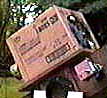
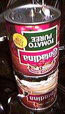
Here's a picture of the above receiver in use with a 10 inch glass lens. The tin can shield can be seen sticking out of the left side of the cardboard box and the entire tin can assembly can be slid in and out of the cardboard box for focusing. This is why the assembly was made up of two cans soldered together. The PIN diode assembly was also made oversize to allow it to be removed and a PMT receiver mounted in a similar tin can to be substituted without changing the mounting arrangement. The PMT receiver is on the large side as it uses one of the huge 2 inch by 6 inch tubes.
The PIN diode setup has outperformed every other system to date proving what you can do with a cardboard box and a couple of tin cans! It doesn't have to look good to work good!
PS - Unfortunately the PMTs (Photo-Multiplier Tubes) I have to work with suffer from severe red droop and the response is severely degraded at 780 to 830 nm where I do most of my experimenting. Even with the degraded performance the PMT WAS my most sensitive receiver. That is until I developed the above PIN diode preamp. The PIN diode now equals the PMT at 815 nm and outperforms it when cooled to - 17 degrees C !
Improvements ?
I only know of two ways to improve the performance of this setup.
# 1 - Locate an FET with a lower noise floor at audio frequencies. Do NOT assume that a good RF device automatically will perform well as an audio device. Many well know RF devices have extremely poor noise figures when used for low frequency 'audio' work. I have been able to improve the performance of the preamp slightly by selecting MPF-102s but these devices seem to be very consistent in performance, meaning that you aren't going to pick up much in the way of performance improvement by selecting devices. I've also tried the 2N3819 with about the same results. Both devices are stocked by Radio Shack.
The second stage contributes little to performance other than gain. However, if you do NOT use a low noise device here it WILL degrade performance. If you can't seem to find either the 2N5088 or 2N4124 device, drop me an Email and I'll mail you a couple! Price is usually approx. $1.00 each plus shipping. I also have PIN diodes available from time to time.
NOTE: When running this system at room temperature, I have found the noise floor is determined by the PIN diode when using this preamp. Because of this, it is doubtful that a lower noise figure preamp will produce any enhancement unless the PIN diode is cooled.
# 2 - Cooling! Yes! You can cool the entire preamp assembly (or just the PIN diode) with remarkable results. Cooling the tin can receiver to - 17 degrees C resulted in the noise floor dropping approx. - 10 dB and the gain went up slightly resulting in a very remarkable improvement in SNR! A good way to do this is with peltier junctions. However, be aware that you will have trouble with moisture condensing on the circuitry which can play havoc with the high impedance circuitry.
NOTE: Since some of my work involves the study of man made light bouncing back from the atmosphere and cloud cover I made no attempt to roll off the low frequency response of this front end. If you want to try this it can be done by reducing the value of the 2.2 uf coupling capacitors and the source bypass capacitor on the FET.
Normally this preamp is followed with three stages of low noise TL-071 op-amps and I do all my bandpass shaping AFTER the preamp. These stages are set up as a low pass, high pass, and an adjustable gain stage. This arrangement was chosen over a simple bandpass filter because most simple bandpass filters generate severe phase distortion with changing amplitude which can cause misleading results when trying to use the phase delay of a BPSK signal to measure distance.
With the PIN diode covered so no light can get to it you should only hear a hiss coming from this front end. If you are hearing any signs of hum check to make sure that the 12 vdc line feeding the preamp is pure DC and that the circuitry is adequately shielded!
Contents of this website are (c)1997-98 of K3PGP and of the originating authors.