The optical output of a laser diode also declines as it heats up. This is reversible as long as no actual thermal damage has taken place. However, facet damage due to exceeding the optical output specifications is permanent. The result may be an expensive LED or (possibly greatly) reduced laser emission.
I accidentally blew one visible laser diode by neglecting to monitor the current but it wasn't the sudden effect some people describe - the current really had to be cranked up well beyond the point where the brightness of the laser beam stopped increasing. It did indeed turn into a poor excuse for an LED. One data point and you can conclude the world. :-)
Another one was blown by assuming that a particular driver circuit would work over a range of input voltages when in fact it was supposed to be powered from a regulated source. At first the degradation in brightness appeared to be reversible. However, what was probably happening was that damage to the laser diode was occurring as soon as the brightness appeared to level off. The natural tendency was then to back off and approach this same point again. Not quite as bright? Crank up the current. Finally, once it is much too late, the realization sets in that it will *never* be quite as bright as it was originally - ever again. This one still lases but at about 1/10th of its former brightness.
If you then try to power this damaged laser diode with a driver circuit using optical feedback, further instantaneous damage will occur as the driver attempts to maintain the normal optical output - which is now impossible to achieve and only succeeds in totally frying the device as it increases the current in a futile attempt to compensate.
Also see the section: How Sensitive are Laser Diodes, Really?.
Believe me, it can get to be really frustrating very quickly blowing expensive laser diodes especially if you don't really know why they failed. This will be particularly true where the specifications of the laser diode and/or driver circuit are not entirely known - as is often the case. Helium-neon lasers are much more forgiving!
Buy one that accepts an unregulated input voltage. Otherwise, you can still have problems even if you run the device from a regulated power supply. All laser pointers and most (but not all) modules will be of this type. However, if you get a deal that is too good to be true, corners may have been cut. A proper drive circuit will be more than a resistor and a couple of capacitors!
To confirm that the driver is regulating, start with an input near the bottom of the claimed voltage range and increase it slowly. The brightness of your laser diode should be rock solid. If it continues to increase even within the supposedly acceptable range of input voltage, something is wrong with either the laser diode (it is incompatible with the driver or damaged) or driver (it actually requires a regulated input or is incorrectly set up for the laser diode you are using). Stop right here and rectify the situation before you blow (yet another) laser diode!
See the chapter: Laser and Parts Sources for a number of suppliers of both diode laser pointers and diode laser modules.
If you still aren't convinced that someone else should deal with laser diode drive design issues, the remainder of this chapter provides suggestions for integrated drive chips, sample circuits, and complete power supply schematics. But don't complain that you haven't been warned of the sensitive nature of laser diodes.
One would think that they all have some kind of power regulator but that apparently isn't the case. Given the downward pressure on prices of these things, it isn't surprising that regulator circuitry will be sacrificed. The manufacturer can sort laser diodes by current versus output power and select a current limiting resistor to be safe for the voltage from a new battery.
You would have to check inside to be sure or make sure you batteries are exactly the same maximum voltage. Even that isn't totally guaranteed as really dreadful designs could depend on the internal resistance of the batteries to limit current.....
To be reasonably safe, you would have to measure the current using a fresh set of the recommended button cells and then add enough series resistance to make sure the current can never exceed this value even with brand new AAs (or whatever you are using).
Note: Free samples of ICs like laser diode drivers may be available for the asking even if you won't be buying a million parts in the future. Manufacturers often provide some means of requesting free samples at their web sites. Just be honest about your needs - they consider it good PR and you might just tell a friend or colleague who WILL buy a million parts!
The MAX3261 (1.2 Gbps), MAX3667 and MAX3766 (622 Mbps), and MAX3263 (155 Mbps) are examples of their highly integrated laser driver chips.
App Note AN52 (and probably others) includes a sample circuit using their one of their chips (not necessary dedicated laser drivers) for powering laser diodes. In AN52, the LT1110 Micropower DC-DC converter is used as the current regulator for operating from a 1.5 V battery.
(From: Steve White (stevew@hitl.washington.edu)).
We are using the OPA 2662 (Burr-Brown) for this. It is an OTA with 370MHz BW, 59mA/ns SR, and can source/sink 75mA of current per channel (two channels per chip which may be paralleled quite easily). The part provides the emitter of the current source to an external pin (programming side of an internal current mirror), so that a single resistor sets the voltage-current transfer characteristic. Watch out for the dependence of the harmonic distortion specs upon the supplied current and frequency though...if this will be a problem for your particular application that is (didn't matter much for mine).
Check out the datasheets for several laser driver circuits available on the market for high speed fiber communications. See Maxim, HP, Sony, Philips, Fujitsu, Microcosm, etc. Also, there are many papers in Bell System Technical Journals that deal with other bias control schemes that don't involve optical feedback.
As far as modulation is concerned, the Analog Devices driver is hard to beat for three bucks. Couple that with a 555 and a battle proven LM317 front end and cry 'BINGO'. Maxim used PECL inputs ... arrgh! I don't need to spit photon packets at 150 mhz! Linear Tech IR receiver looks good, although the $7.00 price tag + a handful of linear doesn't really appeal to me. Too bad you can't get inside the epoxy covered die in the Sharp TV/VCR consumer IR receiver modules (apx $1.50/100 pcs). Not everyone in the world wants to decode bursts of 40 kHz back into data!
Oh, by the way - an Optek BP812 Optologic sensor performs quite well at at 760 nm. It's an active device available in either totem pole or open collector outputs. The applications guy at Optek says the device won't work at 760 but looking at the response curve, I disagree. It's response is only down about 10% in the reds! Most silicon photo stuff is down about 60-75% at 760ish nm. From what I have seen, the device is very usable at 760 nm. Useful part for red diodes and HeNe stuff.
This is getting a little scary. Laser diodes have been around for a good few years now, and I thought it was fairly widely known how you make them go and (harder) keep going for a long time; but there have been several postings recently from folk who are busy making themselves poorer by driving lasers inappropriately. Here are the rules on how you do it right:
         ^ Light Output
         |
         |
         |- - - - - - - - - - - - - - -* ---- Maximum Rated Light Output
         |                            *|
         |                           *
         |                          *  |
         |                         *
         |                        *    |
         |                       *
         |                      *      |
        -|*--*--*--*--*--*--*--*-------+--------------> Forward Current
         |                     |       |
                               |       |<-- Maximum Current
                               |
                               |<-- Threshold Current
The snag is, the difference between threshold and maximum current is usually
quite small; no more than 10% or 20% of the threshold. The threshold current
varies greatly from one device to another (even within the same type number)
and also varies with temperature. Result: setting a fixed current value is
doomed to failure. For some lasers, and on some days, it will be under the
threshold and no laser action will occur; on other days, it will be over the
maximum current and your precious laser will turn into a useless LED (like the
original posting in this thread). The only safe way is to use the monitor
diode current to servo the light output. Even this isn't ideal because the
monitor current is different for different lasers, but:
Sharp (one of the big suppliers of laser diodes) also make some nifty 8-pin drive chips that are pretty good if you don't need to modulate the laser rapidly. For modulation, consider setting the light output close to 50% of full output using a really slooooowww-responding feedback circuit, and then impressing a fixed-amplitude modulating current on the laser. This is OK because the gradient of the light/current graph is reasonably predictable for any given laser type, so it's possible to calculate a suitable safe modulating current from the data sheet.
Good luck to all - and don't forget the eye safety regulations.
(From: Paul Mathews (optoeng@whidbey.com)).
Laser diode structures are usually so small that damage thresholds are very low on every dimension. The general approach to protecting them is to series AND shunt filter (and/or clamp) supply voltages to limit the voltage compliance of current source driving circuits. Also, consider having some of the current limiting be by means of an actual resistor rather than just active circuitry. The parasitic capacitances in active driving circuitry can interact with dv/dt on supply lines to turn on the drive circuit (e.g., drain to gate capacitance with MOSFET drive), so the resistor limits current even when this happens. Using bypass capacitance local to the pulse current loop has the dual benefit of absorbing residual transients and avoiding any effects of upstream series filter components on speed.
(From: Mark W. Lund (lundm@physc2.edu).
You can blow out the laser in nanoseconds if there is enough voltage and/or power in the pulse. Two methods: electrostatic discharge type damage which punches holes in the cavity; brief high power which damages the front facet.
Make sure that the power supply to the modulation circuit is filtered to prevent surges, isolate the signal circuit to prevent surges on the input line from getting to the laser.
There are an infinite number of ways to get a damaging pulse. Most common is the power supply. It helps to have a scope capable of capturing transients for this. The other ones that I will admit to: using a circuit that wasn't grounded to the metal optical table--brushing the table with one line of the circuit and oops; a commercial laser diode power supply that was clean until we used it in computer control mode when it sent out very fast (anhard to see) spikes; hooking the laser up backwards; using a power supply that had a big capacitor across the output which had enough charge in it to do damage; and forgetting to put a peltier cooled laser on a heat sink (the more current I gave the cooler the hotter the laser got....oops.)
Well, that was embarrassing, but I hope it encourages others to save a few (laser diode) lives.
(From: K. Meehan (meehan@srvr.third-wave.com)).
Semiconductor lasers are very sensitive to power spikes. The level of current that is a problem depends on the laser structure and how much of the current is converted into optical power vs. heat. In general, reverse current spikes are very damaging, no matter what level. Make sure that you are modulating the diode so that you go below laser threshold but not below 0V. In the forward direction, very short overshoots (<1microseconds) in current can be handled until you blow the facet off of the device (catastrophic optical damage - COD). Longer pulse overshoots aren't any better. The current level that damage occurs varies from device to device. I tend to recommend less than 10% overshoot in all cases. COD is very easy to note, just look at the laser (while it is not operating) under a microscope. The facet coating is damaged near the emission region, if there is a coating. Otherwise, you will see an enhanced region (darker area) when looking under Nomarski - maybe not so easy to see.
Another problem that you might be having is spiking during start-up or shut-down of the device. Current supplies that look lovely during operation sometimes have spikes in the output when you turn them on or off. You might want to short the device, making sure that there is no bounce during the shorting, before turning your supply on or off. There are several laser diode driver companies out there that make current generators with slow starts and minimal overshoots. Avtech, Melles Griot, ILX, etc.
(From: Alan Wolke (74150.451@CompuServe.COM)).
Welcome to the wonderful world of laser diodes! You'll find that a 5:1 range in monitor current is typical, with even a full order of magnitude being common! This is one reason why most laser diode based applications have a provision for trimming/tuning the driver circuit to the particular laser.
Your safest bet is to design the feedback loop to operate with less than the minimum monitor current, and provide the ability to actively tune it to the appropriate operating point. Thankfully, the relationship between output power and monitor current will remain reasonably constant over the lifetime of each particular device. So, once it is properly set, you're done.
For those of us who have performed the infamous LD to LED (LD->DELD) conversion more often than we'd like, there's an interesting item mentioned near the end of the article: Visible-Laser Driver Has Digitally Controlled Power And Modulation regarding LD drivers. It points out two important characteristics of LDs:
For high speed data and very high frequency RF subcarrier/video work I've always biased my laser diodes to 1/2 laser power then modulated them near 100%, much the same as a standard AM radio transmitter. This does result in a faster response time rather than cutting the LD completely off. It's also probably a bit easier on the laser diode especially if it's a high power unit. (Mine draws 1 amp when putting out 500 mw.)
I never tried biasing it down to BELOW laser threshold at the 'LED' level. Although this would be an improvement over cutting it off completely, I would think this would be slower than biasing to 1/2 laser power.
(From: Sam).
Also see the section: Digitally Controlled Laser Diode Driver which has a bit more on the circuit mentioned above.
    COM o--------------+-------+-------+-------+---------+
                     __|__   __|__   __|__   __|__      _|_
               LEDs  _\_/_   _\_/_   _\_/_   _\_/_ ---> /_\ Photodiode
                       |       |       |       |         |
                       /       /       /       /         +----o PD
                     5 \     5 \     5 \     5 \
                       /       /       /       /
                       \       \       \       \
            1N4002     |       |       |       |
     LD o-----|<|------+-------+-------+-------+
Note that the sensitivity of this photodiode to the LED emission will vary
considerably depending on its position and orientation. Tape the photodiode
and one of the LEDs together (sort of like a homemade opto-isolator) to
stabilize and maximize the response.
Using this 'laser diode simulator', it will really only be possible to confirm that the laser driver current regulator is functional, not to actually set it up for your laser diode.
Once the circuit has been debugged, power down, and carefully install the laser diode. Double check all connections!
Use the guidelines below in both cases (written assuming an actual laser diode is being used):
If you have a (separate) current meter, put it in series with the power supply as well (or provide another means of measuring current).
CAUTION: Use clip leads. Leave the meters in place - do not attempt to change connections while the circuit is powered as this could result in a momentary current spike which may damage the laser diode.
Laser drivers (1) to (3) were from CW laser lights used for positioning in medical applications. Laser driver (4) was from a UPC bar code scanner.
Errors may have been made in the transcription. The type and specifications for the laser diode assembly (LD and PD) are unknown.
The available output power of these devices was probably limited to about 1 mW but the circuits should be suitable for the typical 3 to 5 mW maximum power visible laser diode (assuming the same polarity of LD and PD or with suitable modifications for different polarity units).
Of the 5 designs presented below, I would probably recommend "Laser diode power supply 2" as a simple but solid circuit for general use. It doesn't require any special chips or other hard to obtain parts. However, I would add a reverse polarity protection diode (e.g., 1N4002) in series with the positive input of the power supply.
In fact, funny that you should ask. :-)
An enhanced version of this design including a printed circuit board (PCB) layout is presented in the section: Sam's Laser Diode Driver (SG-LD1).
A very basic and a high power laser diode drive circuit are also included (both open loop - no optical feedback) as well as one that can be programmed for 1024 levels of output intensity.
  Vcc o-----------+------------+-----------------------+--------+------+
                  |            |                       |        |      |
                  |            |    Power Adjust      _|_     __|__    |
                  |            |       R2 10K      PD /_\  LD _\_/_    |
                  |            \     +----+            |        |      |
                  |        R1  /     |    |            |        |     _|_ C2
                  |       610  \     +---/\/\--+-------+        /     --- 1uF
                  |            /     |         |                \ R3   |
                  |            |     |         |                / 15   |
                +_|_           |     |       __|__              \      |
             C1  ---           |     |     E /   \ C            |      |
           22uF - |            +-----|------' Q1  '-------+     +------+
                  |            |     |      2SA1015       |    C|
                  |            |     |       (PNP)        |   |/ Q2
                  |           _|_.   |                    +---|  2SC1959
                  |     VR1  '/_\    |                    |   |\ (NPN)
                  |     2.2V   |     |               C3 +_|_   E|
                  |            |     |             10uF  ---    |
                  |            |     |                  - |     |
                  |            |     |                    |     |
  Gnd o-----------+------------+-----+--------------------+-----+
This circuit lacks some of the protective features of the circuits, below, but
is clearly the same core design. Complete datasheets for Toshiba laser diodes
can be found by under 'Optoelectronics' and 'Visible Laser Diodes' at
Toshiba's Datasheet Search Page.
            D1
  Vcc o-----|>|-------+-----------+-------------------+--------+-----+
           1N4001     |           |                   |        |     |
          Rev. Prot.  |           |    Pwr Adj       _|_     __|__  _|_ C4
                      |           /   R3 10K (2)  PD /_\  LD _\_/_  --- .01uF
                      |       R2  \     +----+        |        |     |
                      |      560  /     |    |        |        |     |
                      |           \     +---/\/\--+---+        +-----+
                      |           |     |         |                  |
                      |           |     |         +-------||---+     /
                    +_|_          |     |       __|__   C2 (1) |     \ R4
                 C1  ---          |     |     E /   \ C 100pF  |     / 3.9
               10uF - |           +-----|------' Q1  '---------+     |
                      |           |R    |    BC328-25 (5)      |    C|
                      |       +---+     |       (PNP)          |   |/ Q2 (5)
                      |       |  _|_.   |                      +---|  BD139
                      |   VR1 +-'/_\    |                      |   |\ (NPN)
                      |   LM431   |     |                 C3 +_|_   E|
                      |   2.5V    |     |               10uF  ---    |
                      |   (3)     |     |X                   - |     |
            R1 3.9    |           |     |Y                     |     |
  Gnd o------/\/\-----+-----------+-----+----------------------+-----+
Note the heavy capacitive filtering in this circuit. Changes would be needed
to enable this circuit to be modulated at any reasonable rate.
Notes:
Since both units were from the same company, I assume that these refinements were added as a result of reliability problems with the previous design - in fact, I have recently discovered that the unit from which I traced that schematic is not as bright as it should be!
Interestingly, there does not appear to be any reverse polarity protection on the input - I don't know why that would have been removed! C1 and Q1, at least, would likely let their smoke out if the power supply was connected backwards.
           2SC517 (NPN) (6)
 Vcc o----+--.  Q1 .---+---------+---------------+--------+----+-----+
          |  _\___/_E  |         |               |        |    |     |
          |     |      |         |              _|_     __|__  \ R5 _|_ C4
       R1 \     |      |         |           PD /_\  LD _\_/_  / 1K --- .01uF
     3.3K /     |      |         /               |        |    \     |  (2)
          \     |      |     R2  \               |        |    |     |
          |     |      |    390  /         R3    |        +----+-----+
          |     |      |         \    +---/\/\---+--+                |
          +-----+      |         |    |   2.2K      |                +
                |      |         |    |             +----||----+      )
                |    +_|_ C2     |    |           __|__ C3 (1) |      ) L1
                |     --- 33uF   |    |   R4    E /   \  47pF  |      ) (3)
                |    - |         +----|--/\/\----' Q2  '-------+     +
                |      |         |R   |  220   BC328-25 (6)    |     |
           C1 +_|_     |     +---+    \           (PNP)        |   |/ Q3 (6)
          1uF  ---     |     |  _|_.  /<-+ R6                  +---|  BD139
              - |      | VR1 +-'/_\   \  | 10K                 |   |\ (NPN)
                |      | LM431   |    |  | Power Adjust   C5 +_|_   E|
                |      | 2.5 V   |    +--+ (4)          10uF  ---    |
                |      | (5)     |    |X                     - |     |
                |      |         |    |Y                       |     |
 Gnd o----------+------+---------+----+------------------------+-----+
Note the heavy capacitive filtering in this circuit. Changes would be needed
to enable this circuit to be modulated at any reasonable rate.
Notes:
It was apparently designed by someone who was totally obsessed with protecting the laser diode from all outside influences - as one should be but there are limits. :-) This one goes to extremes as there are 5 levels of protection:
                             MPSA13
            L1      D1     C       E   I +--------+ O                  -10V out
 +12 o--+--CCCC--+--|>|--+--. Q1  .---+--| LM7810 |--+-------+               o
        |        |1N4002 |  _\___/_   |  +--------+  |       |            C5 |
        |        |    R4 /     |      |      C|      |       |        +------+
        |        |   10K \     |      |       |      |      8| 7  6  5|  180 |
        |        |       /     |      |       |      |     +-+--+--+--+-+ uF |
      +_|_ C10 +_|_ C11  |     |    +_|_ C8   |  C7 _|_    |            |16V |
       --- 2.2  --- 2.2  +-----+     --- .22  |  .1 ---    |   LT1054   |  +_|_
      - |  uF  - |  uF   |     |    - |  uF   |  uF  |     |            |   ---
        |        |     +_|_   _|_     |       |      |     +-+--+--+--+-+  - |
        |        |   C9 ---   --- C6  |       |      |      1  2| 3| 4|  C3  |
        |        | 4.7 - |     | .047 |       +------+-------------+--|--||--+
        |   L2   |  uF   |     |  uF  |       |              C4 |+  - |.01uF |
 Gnd o--+--CCCC--+-------------+------+-------+       180uF,16V +-|(--+------+
It was not possible to determine the values of L1 and L2 other than to measure
their DC resistance - 4.3 ohms. The LT1054 (Linear Technology) is a 'Switched
Capacitor Voltage Converter with Regulator' running at a 25 kHz switching
frequency. A full datasheet is available at http://www.linear-tech.com/.
The input to the LM7810 ramps up with a time constant of about 50 ms (R4 charging C9). This is regulated by the LM7810.
The LT1054 takes the regulated 10 V input and creates a regulated -10 V output. There is no obvious reason for using this part except the desire to isolate the laser diode as completely as possible from outside influences. Like the use of an Uninterruptible Power Source (UPS) to protect computer equipment from power surges, a DC-DC converter will similarly isolate the laser diode circuit from any noise or spikes on its input.
The second part of the circuit is virtually identical to that described in the section: Laser Diode Power Supply 1 (RE-LD1):
  Gnd o----------------+------------+------------------+-------+-----+
                       |            |                  |       |     |
                       |            |     Pwr Adj     _|_    __|__  _|_
                       |            /      R2 20K  PD /_\ LD _\_/_  --- C2
                       |        R1  \     +----+       |       |     |
                       |       470  /     |    |       |       |     |
                       |            \     +---/\/\--+--+       +-----+
                       |            |     |         |                |
                     +_|_           |     |       __|__              /
                  C1  ---           |     |     E /   \ C            \ Rx
                10uF - |            +-----|------' Q1  '-------+     /
                       |            |R    |       PN2907       |    C|
                       |            |     \       (PNP)        |   |/ Q2
                       |           _|_.   / R3                 +---|  PN2222
                       |      VR1 '/_\    \ 1K                 |   |\ (NPN)
                       |      LM385 |     /               C1 +_|_   E|
                       |      Z2.5  |     |             10uF  ---    |
                       |            |     |X             16V - |     |
                       |            |     |Y                   |     |
 -10 V o---------------+------------+-----+--------------------+-----+
Note the heavy capacitive filtering in this circuit. Changes would be needed
to enable this circuit to be modulated at any reasonable rate.
I suspect that there are additional components inside the laser diode assembly itself (like the hypothetical Rx, probably a few ohms) but could not identify anything since it is totally potted.
The schematic for the driver is available in both PDF and GIF format:
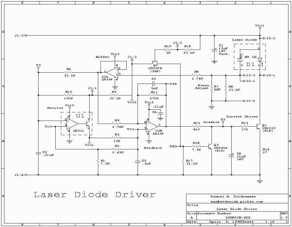
The feedback loop consists of the photodiode (PD, part of D1), a non-inverting buffer (U2A), the inverting amp/low pass filter (U2B, R9, R11, C2, bandwidth of about 1 kHz), and emitter following current source (Q1, R13, R14, with a sensitivity of 36 mA/V) driving the laser diode (LD, part of D1).
Separate DC inputs are shown for the laser diode/photodiode itself (Vcc1) and the other circuitry (Vcc2). Vcc1 must be a regulated supply as there is no on-board voltage reference. It appears as though Vcc1 and Vcc2 should be set equal to one-another though there may have been (external) power sequencing in the original application. If Vcc1 is less than Vcc2 by more than a volt or so, the laser diode will be turned off. The input voltage range can be from 5 to 12 VDC though I would recommend running on 5 VDC if possible since this will minimize power consumption and heat dissipation in the current driver transistor and other circuitry. This is adequate for laser diodes with an operating current of up to about 80 mA. For laser diodes with an operating current greater than this, a slightly higher voltage will be required.
The set-point is at about 1/2 Vcc1 so that the laser diode optical output will be controlled to maintain photodiode current at: I(PD) = .5 Vcc1 / (R6||R7). Use this to determine the setting for R7 (SBT, Select By Test, Power Adjust) for the photodiode in your particular laser diode. Or replace R7 by a low noise variable resistor and