The TEXAS LF Beacon
Photos courtesy of Greg Raven, KF5N
Converted to HTML (with permission) by K3PGP v1.0
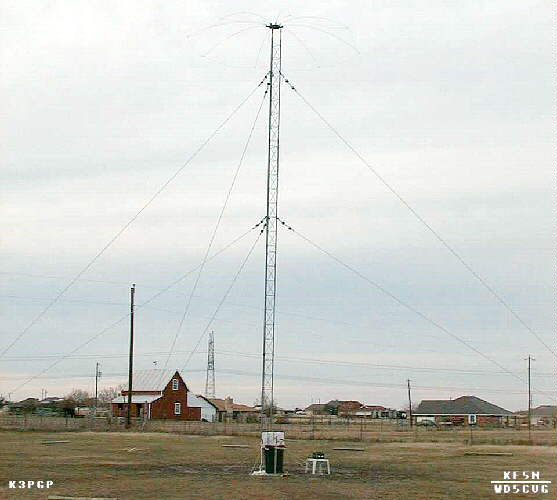
Photo of the TEXAS
beacon tower including the top-hat.
The atomic clock used for modulation and frequency
stability is located indoors via buried cable.
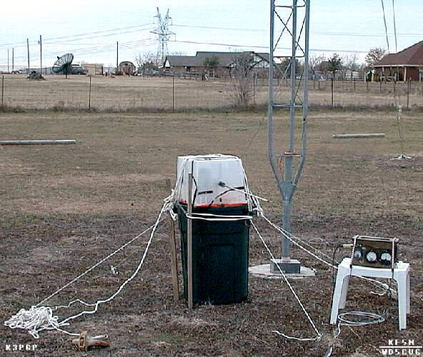
Photo showing
base-loading coil, tower base, and ammo-box transmitter.
Landscaping timbers form the ends of "radial
spokes" that hold down rolls of
chicken-wire for the ground plane.
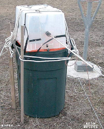
Close-up of the
variometer (variable base-loading coil) inside the plastic
container on top of the trash can. The wooden dowel
protruding from the container
is used to adjust the inductance value for resonance. The tower's
base
insulator can be seen to the right.
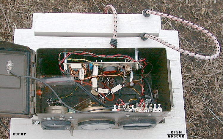
Photo of the ammo-box transmitter.
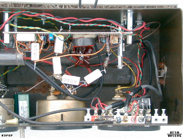
Close-up of the ammo-box transmitter. The string of power resistors are "Rsource". The power diodes at bottom right, and the ICs standing on end with wires soldered down their edges are ESD / lightning-surge protection devices. "Lrfc" is the toroidal inductor located in the center of the board. The collection of silver mica capacitors is "Cshunt". The antenna current sampling transformer is clipped onto the red wire that exits through the plastic tube to the left (partially obscured by the power resistors), to go to the loading coil outside. Looks messy, but works great!
For details on "Rsource", "Lrfc", "Cshunt" and other items, see:
How to Design a Class-E Transmitter for Your LowFER Beacon
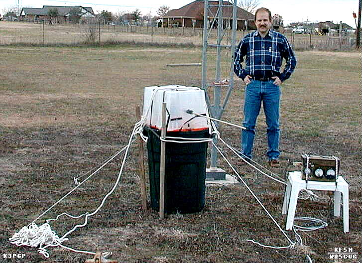
Bill Cantrell, WD5CVG with the TEXAS Beacon
This experimental beacon operates on 189.700 kHz with a power of 1 watt (input) per FCC Part 15 Regulations.
Contents of this website are (c)1997-99 of K3PGP and of the originating authors.
NOTE: You may link to this page but you may NOT copy without permission from the author and K3PGP
To contact the author of this article: Email Bill Cantrell
-=<EOF>=-