Back to Sam's Laser FAQ Table of Contents.
Amateur Laser Construction
Sub-Table of Contents
Back to Sam's Laser FAQ Table of Contents.
Back to Amateur Laser Construction Sub-Table of Contents.
Introduction to Amateur Laser Construction
In this chapter and the one that follows, we provide basic information on the
construction of various types of lasers from scratch.
Extensive basic information is provided on home-built laser safety, setting up
a home laser lab, sources of supplies and chemicals, vacuum systems, glass
working, structural materials, power supplies, and more.
Then, a variety of specific types of home-built lasers are described in more
detail. Much of this material is derived from the Scientific American
collection "Light and its Uses" [5] and from the email, Web sites, articles,
and experiences of those who have been successful in building their own lasers
from basic components and getting them to work (not taking the easy way out
and using commercial tubes or laser diodes!) - or have given it their best
shot trying!
While this will not substitute the hands-on of actually having built one of
these lasers or detailed construction plans, it may provide the spark to get
you started!
First, let us consider some ill-posed justifications for attempting to build a
laser from (almost) raw materials:
- Something can be put together quickly. Forget it. Any of the types of
lasers considered in this discussion will require many many hours, more like
months, to locate the materials, chemicals, and other supplies and to
construct, align, and get working - if you ever succeed at all.
Furthermore, you will be CONSTANTLY fiddling with adjustments like gas fill,
mirror alignment, power supply voltage/current. In many cases, total laser
lifetime is often short (a few hours) before a total rebuild is needed.
These are not generally set-it-and-forget-it type equipment! If you just
want a working laser, this is definitely NOT the way to go.
- Lasers are SO expensive. Yes in many cases, but what you get is something
that works (relatively) reliably with (relatively) minimal fiddling with
adjustments. In the end, you will likely spend more than you might think
based on your initial estimates simply because you cannot go and buy just
the quantity of materials or chemicals that you will need - 1 screw or 2
inches of pyrex glass 5 mm ID tubing or 6 feet of #24 magnet wire, for
example.
A $25 1 mW helium-neon laser and power supply, or $19.95 diode laser type
laser pointer may be satisfactory for your needs. These will be even less
expensive if you build your own power supplies - and orders of magnitude
easier than building an entire laser from scratch.
If these are your only reasons for wanting to do this, you will rapidly tire
of the endeavor and the parts will end up in a box alongside that dusty old
partially ground telescope mirror you also never completed :-(.
However, there are many justifications for embarking on an adventure of this
type:
- Educational experience. I guarantee that you will learn a tremendous amount
in the process - even if your baby never actually produces a beam. You will
need to deal with a variety of disciplines (depending on the type of laser)
possibly including: glass working, vacuum and gas supply systems, machining,
design of high voltage power supplies, optical alignment, sensors, and more.
The effort and contact with multiple discipline may stimulate interests in
other areas as well.
- Challenge. It probably goes without saying that the production of coherent
light - even if for a short time - from a totally homemade laser represents
a tremendous achievement with enormous satisfaction value. Why do people
climb mountains? Building a laser is like climbing from the depths of the
Pacific to the top of Everest and beyond. Note: If you don't believe this
then you will probably not have enough motivation to complete the project!
- Experimentation. There are many things you can try with full access to both
the inside and outside of the laser resonator that are impossible with a
sealed HeNe or Ar/Kr ion tube. Variations on the lasing medium including
(for gas lasers) the types and pressures of the gas fill or (for dye
lasers), the types and concentrations of dyes themselves; types of
excitation (direct discharge, RF, light); alternative optics like curved and
plane mirrors, prisms, lenses, and coatings,
Note: There may be some reduncdancy with some of these photos as they may be
present on multiple locations including the Amateur Laser Constructors Web site.
(From: Chris Chagaris (pyro@grolen.com)).
(From: Thieu Asselbergs (asselber@fys.ruu.nl)).
(From: Laserist (laserist@geocities.com)).
These drawings show the structure and power supplies for some of the lasers
built by amateurs. These diagrams are based on the laser articles from
Scientific American (including the book: "Light and its Uses" - see the
section: Light and its Uses - Table of
Contents for an explanation as to why copies of or links to the original
artwork could not be provided). Their purpose is to give you a flavor of what
this type of laser construction entails - but are NOT intended as dimensioned
plans and are NOT drawn to scale. Refer to the more detailed description in
the chapter: Home-Built Laser Types,
Information, and Links and the relevant Scientific American articles.
Start by locating back issues of Scientific American and/or their reprint
collections such as "Light and Its Uses" [5]. There have been many practical
articles and Amateur Scientist columns on lasers, laser construction, and
other laser related subjects, particularly during the initial laser craze of
the 1960s and 1970s but extending to the present particularly for more exotic
types of lasers and laser applications. A large public or university library
will likely have all of these somewhere though you may have to request them
from their storage vaults and/or they may be on microfilm or microfiche.
See the section: Light and its Uses - Table of
Contents for a list of all the articles that constitute this valuable
collection and an explanation of why I cannot provide on-line access to it.
Here is a list of some of the laser articles that have been published in the
Amateur Scientist columns of Scientific American. The first 7 of these
constitute the chapters on laser construction found in "Light and its Uses":
- Helium-Neon Laser, September, 1964, pg. 227.
- More on the Helium-Neon Laser, December, 1965, pg. 106.
- Argon Ion Laser, February, 1969, pg. 118.
- Tunable Dye Laser, February, 1970, pg. 116.
- Carbon Dioxide Laser, September, 1971, pg. 218.
- Infrared Diode Laser, March, 1973, pg. 114.
- Nitrogen Laser, June, 1974, pg. 122.
- Mercury-Vapor Laser, October, 1980, pg. 204.
- Copper Chloride Laser, April, 1990, pg. 114.
Except for the one in (6) which for all practical purposes you can ignore (it
tells you how to hook up a long obsolete type of laser diode), all the others
are built from the ground up using basic materials (i.e., glass tubing, pieces
of plastic and metal, mirrors and other optics, glue, duct tape, various
bottled gasses and other chemical supplies, high voltage transformers,
resistors, capacitors, diodes, wire, etc.).
As an aside, I lament the fact that few of the more recent Amateur Scientist
columns have nearly as much sophistication and depth as those from that era.
On the other hand, experiments that are presented may be performed by nearly
anyone who is reasonably handy using parts from the local home center and
Radio Shack and yet this is definitely real science. There is no need for
high vacuum systems, glass working skills, strange gas mixtures and other
chemicals, or fancy test equipment!
While the Scientific American Web site has many interesting articles, they do
not go far enough back to be of much use for laser construction. There is an
Index to the Amateur Scientist articles maintained by the Society of Amateur
Scientists (SAS) or see the section: Light and its Uses - Complete Table of
Contents. However, the articles are not on-line (see the explanation
there of why this was not possible) so you still have to do the leg-work!
The Society for Amateur Scientist (SAS) Web site includes among other
things, a technical forum devoted to the interests of, you guessed it, amateur
scientists like you:
Laser specific traffic on this forum is quite small but the high chance of
finding someone with similar interests balances this out to some extent!
Check out the Amateur Laser Constructors Web site and the other links to
home-built lasers and related projects in the section: Amateur Laser
Construction/Laser Communications Sites and Links to see what others have
done. Contact them via email. One thing is certain: since there are so few
hobbyist types interested in this sort of thing anymore, these people should
jump at any opportunity to discuss their passion to build lasers with you.
The site also has a variety of useful links and pointers to Scientific
American and other articles on lasers and related topics.
Information Unlimited has what are supposedly complete plans argon ion,
carbon dioxide, nitrogen, copper vapor, and tunable dye lasers. (In the case
of the CO2 laser, they have parts, kits, and completely assembled versions as
well - supposedly.) I doubt that it is coincidental that these are also most
of the types of lasers covered in the Amateur Scientist columns of Scientific
American! I do not know whether if the plans are of any value beyond those
or whether they are indeed just poor reproductions or transcriptions. I also
have no idea of whether what they provide is credible for the price or whether
it is likely to result in a successfully completed project. Also see the
section: Electronic and Laser Project Parts, Plans, Specialized Components
for additional comments about Information Unlimited.
MWK Industries also has plans
for most of the types of lasers included in "Light and its Uses". As with
the plans, above, I do not know if these are derived from there or elsewhere
or whether there is any benefit to buying these as opposed to digging up the
info in "Light and its Uses" in conjunction with this document!
Thanks to Chris Chagaris (Email:
pyro@grolen.com) for his comments and
additions to this document. His first-hand experience in constructing several
lasers from scratch has been extremely valuable in polishing and enhancing
this and the chapter on Home-Built Laser Types,
Information, and Links that follows.
Back to Amateur Laser Construction Sub-Table of Contents.
Setting up a Home Laser Lab
There are a variety of issues that are important for any sort of home lab
or workshop but the following, in particular, apply directly to lasers and
laser construction:
- Laser safety. In some ways, a homebuilt laser is MORE dangerous in terms
of risk to vision (at least) compared to a commercial one. One reason is
that the output power and behavior is less predictable - and there are no
manufacturer's specifications for MAXIMUM output. Therefore, one must err
on the side of caution - assume that they are at the upper end of any
possible range of power outputs. For all except the CO2 laser, these will
at least be well into the Class IIIb range. The CO2 WILL be Class IV! This
doesn't mean you will get an eye-killer beam from your laser - just that you
cannot safely assume you WON'T!
See the chapter: Laser Safety for more information.
- High voltage. The power supplies for these lasers almost all involve high
voltage at significant current and/or with sizable high voltage filter or
energy storage capacitors.
- The neon sign/luminous tube transformers often used for excitation of gas
lasers come in various sizes but are all potentially lethal. The larger
ones, even more so.
- Any time you are storing energy in multi-KV storage capacitors, you are
talking about seriously deadly equipment.
- Even little high voltage inverters running off some AA batteries can
generate deadly output - especially where a capacitor is involved.
Read and understand the information in the document: "Safety Guidelines for
High Voltage and/or Line Powered Equipment" BEFORE constructing and powering
any of these systems.
- Water/liquids. The CO2 laser will require water cooling. You may want to
add water cooling to others like the Ar/Kr laser to boost output power. The
dye laser involves the use of liquids - some of them quite nasty. All use
high voltage AC line connected power supplies. This makes these doubly
dangerous. Make sure all precautions are taken including proper wiring and
grounding of all equipment AND plumbing! Even though the HV discharge is
supposed to be between special electrodes, it can jump to nearby metal
fittings - and you!
- Vacuum vessels. The potential energy of the atmosphere working on a vacuum
is enormous. Every square inch of surface area separating the atmosphere
from an evacuated volume represents 14.7 pounds of force. A gallon jar with
the air pumped out may have over 1.5 TONS of force attempting to crush it.
The results of an implosion can be spectacular and are something you don't
want to experience first-hand.
Note that it is the difference between atmospheric pressure and that of your
vacuum that determines the stress on the container - whether you are pumping
down to 10 Torr or 1E-14 Torr is for all practical purposes irrelevant with
respect to implosion risk!
- Toxic/corrosive chemicals. Some of the materials used for glass cleaning,
electrode coatings, and organic dyes (for dye lasers) are extremely toxic,
corrosive, or both. Make sure you understand the chemical safety issues.
- Poisonous chemicals can get picked up on cleaning materials, clothing,
surfaces of lab glassware, tabletops, storage cabinets, the bottom of
your shoes, etc.
- The fumes from these chemicals are likely to be toxic and irritating as
well.
- Flammable or suffocating gasses. While the actual quantities of gasses used
in most of these lasers is infinitesimal (since they operate at a very small
fraction of atmospheric pressure), some gas will escape and leaks can
occur.
- These are all colorless and most are odorless so there will be no visible
signs of a leak or buildup of fumes.
- Proper ventilation must be provided
- Gasses that are heavier than air in particular can hang around resulting
in a layer that you cannot breath or one that is flammable.
- Glassworking, annealing, and outgassing flames. Needless to say, any time
that open flames are used, precautions must be taken to assure that no
flammable materials are in the vicinity.
- Obviously, this includes the chemicals and gasses mentioned above.
- Shavings from wood and plastic gutting, filing, grinding, and sanding are
extremely flammable and should be completely cleaned up and removed before
lighting the propane or oxy-hydrogen glass working torch!
- Have a fire extinguisher of the proper type - rated for chemical AND
electrical fires - in a location that is accessible outside the range of
any possible fire. Make sure you cannot be trapped by a fire. Two fire
extinguishers and two means of egress at opposite ends of the lab are
even better.
There didn't appear to be a critical mass of lawyers present at the time most
of the articles in "Light and its Uses" were written. Therefore, they tend
not to deal with the safety issues as emphatically as might be desired. Most
of these projects have aspects (most often the high voltage power supplies)
that are potentially dangerous or lethal. Safety must be at the top of your
list of priorities when undertaking such an endeavor!
Since any of these lasers represents a long term comittment, it is essential
that an area be set aside for your laser lab. Therefore, the kitchen or
dining room table is NOT an appropriate place to be constructing a laser.
It is possible to do without the sort of setup depicted in the section:
Possible Laser Lab Layout but there are some basic requirements for a
safe, functional, and convenient space:
- An area that is as dust free as possible is absolutely essential. Dirt,
dust, condensed tobacco smoke or cooking grease, or other contamination of
optical surfaces is a major cause of problems in getting a laser to work
and/or result in reduced output power or erratic operation.
Forget about smoking around precision optics. Aside from slowly killing
yourself, a miniscule amount of tobacco smoke residue will play havoc with
mirrors and lenses - especially inside the laser resonator. You will be
wasting your time or worse. Just because you saw a demo where someone
blew smoke in the path of a laser beam to make it visible is no excuse as
that was just a one-time demo. There are special means of generating
smoke for this purpose which are non-toxic and do not condense on optical
surfaces should a real need arise.
- You must be able to leave it undisturbed probably for weeks or MONTHS on
end. Therefore, a spare room is best. You definitely don't want to share
your lab with a woodworking or gardening operation. Or, your kid brother
who likes to wreck EVERYTHING! :-)
- There must be access to electricity. A pair of dedicated circuits with
local cutoff switches/circuit breakers is nice. Install outlet strips all
along the walls behind your work surfaces.
- There probably needs to be running water and a drain. Where chemicals are
involved, the drain should be direct to a sewer, not a sump - assuming you
can safely put them down at all.
- There must be adequate ventilation. However, there should be NO way for a
laser beam to escape to the outside world! This means there can be no
open or uncovered windows! And, if your laser accidentally drills a hole
through your stone and stucco exterial wall, patch it up as quickly as
possible. :-)
- Minimization of fire and water damage risk. This is mostly common sense
meaning a room with a concrete or vinyl floor and NO curtains or drapes.
A room in a dry basement is probably best if it can be made reasonably
dust-free.
- It must be large enough to provide space for you, the laser itself AND
for any additional length required by alignment or other optical add-ons
to the laser. Also, don't forget creature conforts for your guests like
a sleep sofa (for when you are performing critical mirror alignment),
stereo, big screen TV - OK, just kidding. ;-)
- Storage. There can never be too much. You need to be able to handle all
sorts of components, electronic and optical assemblies, partially or fully
completed lasers or other apparatus, chemicals, and other supplies.
- Metal double door supply cabinets are ideal for larger items and for
holding the multi-drawer parts cabinets you will also need (see below).
These are typically 18" to 24" deep by 36" wide and 60" to 78" tall with
multiple adjustable shelves. The larger the better if you have the
space. I have gotten mine from garage and tag sales in good condition
for between $10 and $40 (they retail for over $200).
Of course, other kinds of cabinets are fine as well. However, anything
you chose should have doors to minimize dust on optical and electronic
components and assemblies.
- Small cabinets with 24 to 50 plastic drawers are most convenient for
electronic, optical, hardware and mechanical parts. One with 50 drawers
can typically be purchased for $10 to $15. I prefer where all the
drawers are the same size - those with multiple size drawers seem just
plain silly. :-)
- File cabinets with half-height (index card) drawers and blue print
cabinets are excellent for tools and parts as well. These are
unbelievably expensive if purchased new but sometimes turn up at estate
sales and the like for a song (because most people cannot think of a
good use for them!).
- The wall space above your optical or electronics benches can also be
utilized by adding some shelves or even those recycled kitchen cabinets
(which are even better since they have doors!).
I wish I had this! Note: Two means of exit and two fire extinguishers!
Also note the chair - most important - and the bench for your guest (though
probably should be s eleep-sofa so they can snooze while you spend the
afternoon adjusting your gas mixture or performing mirror alignment. :-)
    |<------------------------------- 12' ------------------------------>|
 ___|____________________________________________________________________|
  ^ |    |                                                         |     |
  | |    |        Storage Cabinets/Shelves (above work area)       |     |
  | |    '---------------------------------------------------------'     |
  | |          Electrical Outlets (two circuits) all along wall          |
  | |                                                                    |
  | |            Work Surface - thick hard-plywood (3' x 12')            |
  | |____________________________________________________________________|
  | |           |                                                        |
  | |           |  Vacuum System on floor (beneath work area)     Gas    |
  | |           |                                              Cylinders |
  | | Test      |                                              __________|
  | | Equip.,   |                    ________                 |          |
  | | Power     |                   |        |                | Wet area |
    | Supplies, |                   | Office |                | Glass-   |
 10'| Misc.     |                  (| Chair  |)               |  working |
    |           |                   |________|                | Ventila- |
  | |           |                   '--------'                |  tion    |
  | |___________|                                             |__________|
  | |                                                                    |
  | |S Power Switch            _ _        __________                     |
  | |(on Wall)          .-======'======-.|          |                    |
  | |        /          |               ||  Bench   |           \        |
  | |      /       Fire |    Storage    ||          | Fire        \      |
  | |    /         Ext. |               ||==========| Ext.          \    |
 _v_|__/         _______|_______________|____________________         \__|
- Lab equipment - Scientific supply companies. Surplus outfits.
- Glassware including glass tubing - Scientific supply companies. Some large
hobby shops may have some of this as well but the quality may be poor.
- Gasses - Chemical supply companies, Gas supply companies (e.g., AirCo),
Welders and welding supply companies, neon sign shops and supply companies.
- Chemicals - Chemical supply companies, high school/college teaching or
research labs, your local grocery, pharmacy, hardware store, home-center,
and supermarket! Not all chemicals are exotic and hard to find!
- Electrodes - Neon sign shops, fabricate your own
- Optics - New, surplus, salvage (e.g., broken HeNe laser tube to obtain
dicroic mirrors). Check out the various suppliers listed in the chapter:
Laser and Parts Sources. Note: A basic requirement for going through
life should be at least one trip to to the Edmund Scientific's outlet store!
- Mirror alignment jig. It is a simple matter to make your own. For these
relatively wide bore lasers, this can be done using simple materials (like
cards with holes punched in them, flashlight bulbs, and microscope slides.
Or, if you have an HeNe or collimated diode or other working laser, using
that for a light source. There are at least two alternative basic parts
type designs in "Light and its Uses" and laser based designs in the
chapters: Helium-Neon Lasers and Argon/Krypton Ion Lasers.
- Structural materials - Scrap/salvage/junk yards, Lumber yards, Home-centers,
Machine/metal shops. Sometimes common household items are overlooked - be
creative.
Develop a relationship with a teacher/instructor/professor/researcher at a
high school/technical school/college/university/industrial lab. Some people
will be more than eager to help and mentor you - even to the extent of loaning
equipment or donating small quantities of chemicals, electronic components,
hard to find optics, etc. to your cause. Use of their lab may even be
possible. There are various programs as well to encourage students to go into
science and technology fields. Who knows, they may even pay you to do this!
Call up laser and optics manufacturers. Sure, many won't give you the time of
day unless they think you will be ordering $1,000,000 worth of equipment.
But, all you need is one to say yes! There are always such things as cosmetic
rejects or seconds - that are useless to them because they cannot sell the
parts - but fine for your needs. The trick is to hold their attention long
enough - or be such a (polite) pain in the neck that the easy way out is for
the company to provide what you want! I have heard of people obtaining all
sorts of material, parts, equipment - some of it quite expensive - in this
manner.
In summary - possible places to find useful stuff:
- Household items.
- Scientific equipment/chemical supply houses
- High school/college/university labs
- Industry, particularly laser, optics, and scientifically oriented companies.
- Metal, wood, and plastic fabricators, neon sign shops.
- Garage sales, flea markets, hamfests, thrift stores, etc.
- Hardware stores, home centers, pharmacies, variety stores, supermarkets.
(From: Chris Chagaris (pyro@grolen.com)).
Here are a couple of resources that I have not seen mentioned anywhere on the
Net:
For chemicals used in various aspects of laser construction and laboratory
glassware at unbeatable prices, a fine source is:
- Hagenow Laboratories Inc.
1302 Washington Street
Manitowoc, Wis. 54220
Phone: 1-920-683-3339
This company has been in business since 1953 and does welcome orders from
individuals. Some of the materials that may be of interest to the laser
constructor are: Methyl and ethyl alcohols for dye laser solvents, copper
chloride for the CuCl2 laser, mercury metal for vacuum work ($7.25/4 oz.!),
and West type, glass, condenser tubes with water jackets up to 600 mm in
length, for use as plasma tubes in CO2 laser construction.
For quartz tubing and quartz windows of all sizes, at very good prices, may
I suggest:
- G. Finkenbeiner Co.
33 Rumford Ave.
Waltham, MA 02154
Phone: 1-781-899-3138
Fax: 1-781-647-4044
Email: GFIglass@aol.com
Web: http://www.finkenbeiner.com/
I have dealt with them personally and found them to be very receptive and
helpful. They, of course, also do precision glasswork of all kinds and
specialize in working with quartz.
On a side note, they are the only manufacturers in the world of Ben
Franklin's invention..... The glass harmonica!
I would be glad in assisting other individuals in locating some of the more
difficult to procure items needed in some aspects of constructing these
various lasers.
(From: Steve Roberts (osteven@akrobiz.com)).
If you are into building your own HeNe (or other) laser from the ground up,
these suppliers may come in handy.
- Coherent Auburn Group.
- Spectra-Physics, a large-frame HeNe maker, might be willing to donate/sell
at cost. 1-415-966-5576
- Dale Harder of H and H Lasers, Inc., Cleveland, Ohio (sorry, don't have his
current phone number). He rebuilds large HeNe lasers (up to 120 mW) and
knows what you need and probably has old ones.
- Holo Spectra, Inc., phone: 818-994-9755. Contact Bill Arkin.
- Midwest Laser Products, phone: 708-460-9595.
- Meredith Instruments, phone:
602-934-9387.
(From: Joe or JoEllen (joenjo@pacbell.net)).
A good resource for components found in "Light and it's Uses" is:
- North Country Scientific
RFD 1
Plymouth, NH 03264
Phone: 1-603-726-3532
I just spoke to the owner-nice fellow. He says he still has inventory of
some nitrogen, argon, dye, and Hg Vapor laser components but interest is
dwindling so I don't know how much longer he will be in business. His
prices are very good also.
Back to Amateur Laser Construction Sub-Table of Contents.
Introduction to Vacuum Systems and Technology
This and the sections that follow represent the barest introduction to vacuum
technology and systems. See The Electronic Bell Jar for additional articles,
links, and references on vacuum technology of relevance to the hobbyist and
experimenter. In particular, Vacuum Basics provides a nice introduction
including vacuum terminology and applications.
Its parent site, the Bell Jar has an index to many additional articles
available only in hard copy and/or by subscription.
There have also been a number of articles on vacuum systems and technology in
the Amateur Scientist column of Scientific American. See the Index to the
Amateur Scientist articles maintained by the Society of Amateur Scientists.
These include:
- Vacuum pump, December, 1958, pg. 134.
- Vacuum pumps, March, 1960, pg. 187.
- Vacuum leak detection, February, 1961 Feb, pg. 159.
- How to make a Valveless pump, January, 1965, pg. 118.
- How to make a McLeod gauge, December, 1965, pg. 106.
All but one of the gas lasers described in chapter: Home-Built Laser Types
and Information require a decent vacuum system to remove air from the laser
tube so that it can be back-filled with the required lasing gasses at a low
pressure - a vacuum. These include the HeNe, Ar/Kr, CO2, HeHg, and CuCl/CuBr
lasers. The N2 laser requires only a 'low' vacuum since it runs at a
substantial fraction (e.g., perhaps 20%) of atmospheric pressure and some
versions can run ambient pressure (1 atm).
The vacuum system serves three functions:
- Remove (nearly) all the air from the apparatus. For almost all the gas
lasers we will be describing, air is poison. It must be purged from the
tube before the required gasses can be admitted. Only with most of the air
gone, can proper and efficient lasing action to take place. Even a small
amount of residual air may result in erratic or weak operation - or no
output beam at all!
- Pump out residual gasses resulting from outgassing from the glass, seals,
adhesives, finger prints, and other contamination on the surface and in the
crevices of the laser tube assembly. Some materials like vacuum grease do
not cause problems. However, a single finger print can represent a
veritable reservoir of unwanted vaporous contamination!
- Control the pressure of the gas fill as individual gasses or gas mixtures
are admitted to the apparatus either prior to or during operation as the
electrical discharge buries gas molecules under sputtered electrode material
or chemical reactions affect the proportion of each type of gas.
By the standards of the vacuum industry, our requirements are modest and are
not really termed a 'high' vacuum but they are still not the sort of thing
you come across in daily life.
But first, how about all this talk of pressure?
We always hear about the barometric pressure - or the level of a vacuum - in
terms of 'mm or mercury' or 'inches'. 1 atmosphere (at sea level under some
unidentified ideal conditions) is also said to be 14.7 pounds per square inch.
Why?
The earth is covered with a vast ocean of air. Despite common experiences,
even air has mass and mass implies weight. We know it has volume or else
your automobile would have a real problem with flat tires. Most of the volume
(the contribution from the volume of the the protons, neutrons, and electrons
in the atoms are negligible but not precisely zero) results from the constant
motion of the molecules (in air or other gas) bouncing against each-another
due to their thermal motion. This also keeps the air in a gaseous state. At
really low temperatures, the motion is reduced resulting in liquid and solid
phases of even air. At exactly absolute zero (-459 degree F or -273 degrees
C) all motion ceases. However, even then most of the volume of the frozen air
is still empty space - but that is another story.
At sea level under average conditions, the column (actually an inverted
truncated pyramid if you want to be strictly correct) of air above 1 square
inch of area would weigh 14.7 pounds if you could capture, compress, and
package them and plop them down on a delicatessen scale! As you move away
from the earth, this 'column' of air becomes increasingly rarified approaching
a prefect vacuum at 50 miles or so - else low earth orbit satellites would not
stay up very long due to air friction.
It turns out that a column of mercury with an area of 1 square inch and
29.92 inches (760 mm) high weighs exactly 14.7 pounds as well (what a
coincidence, huh?). So, if you take a closed-end tube a little more than
30 inches long, fill it with mercury, and invert it in a pool of mercury,
the pressure of the surrounding air will be able to support a column of
mercury 30 inches high. The space above the mercury will be a decent vacuum.
You have made a mercury barometer.
If you were to take this barometer and place it inside a vacuum vessel and
start up the pump, the column would go down until at the point of a perfect
vacuum (not achievable but close), it would be precisely level with the
surrounding pool of mercury.
Note that the diameter of the tube doesn't matter - wider implies a heavier
column of mercury but the area of the air acting on the column changes by the
same factor. In fact, it can have pretty much any convoluted shape you want
(except that if portions are too thin, surface tension becomes a factor) as
long as it is sealed and totally filled with mercury. Why this is so is left
as an exercise for the student!
The corresponding height of 1 atmosphere for water is about 34 feet - a column
of water with a cross sectional area of 1 inch and height of 34 feet weighs
14.7 pounds. This also means that for a diver, the water pressure increases
by 1 atm for each 34 feet of depth. Thus it is not surprising that there are
significant problems in deep sea diving! You have to go up by MILES in air
for the pressure to decrease by a substantial fraction of 1 atm but need only
go down 34 feet in water to increase pressure by 1 atm!
Note that the most likely form of a pressure you are familiar with is the
reading on the gauge you use when checking or filling your automobile or
bicycle tires. However, this is calibrated relative to the surrounding
pressure of around 1 atm. Thus, the actual pressure inside a tire will
actually be 1 atm + the reading on the gauge. And you thought you had a
perfect vacuum inside that flat tire when the reading was 00.0! :-)
Vacuums come in all shapes and sizes - and I am not referring to vacuum
cleaners! Any local reduction in air pressure significantly below standard
atmospheric pressure (760 mm of mercury, 14.7 pounds per square inch) is
termed a vacuum (except by your local weather person who talks about 'low
pressure areas'). For convenience (and because there must have been a meeting
of elder statesman with nothing better to do), the Torr in honor of some
Italian named Torrecelli is used to designate a pressure of 1 mm of mercury
I guess referring to 'Torrecellis' all the time would be too confusing. :-)
The Vacuum Chart provides a nice instant summary of pump types, gauges, and
applications, as a function of the level of vacuum.
The following dividing lines between low, medium, high, and ultra-high vacuums
are somewhat arbitrary but will be convenient for discussion:
- Biosphere: 1 atm (760 Torr) to .5 atm. At sea level, the average pressure
is about 1 atm. The weather person will talk about 'inches of mercury'
instead of 'mm of mercury' since most people in the U.S.A. at least haven't
entered the metric age. :-) 29.92 inches = 760 mm. The wildest storm
imaginable doesn't produce variations beyond a few percent of this nominal
value.
Mountain climbers have to endure reduced pressure and above about 10,000
feet, require breathing equipment. Anyone who has traveled by air knows
the standard speech at the beginning of each flight "....should oxygen be
needed, the compartments overhead....". This would also happen above about
10,000 feet.
Astronauts on American spacecraft (at least they used to), breath unaided at
a pressure of perhaps 1/5 of an atm because they breath nearly pure oxygen.
Since in the normal atmosphere, oxygen is only about 18 percent of the total
mixture (most of the rest is nitrogen with a little CO2 and inert gasses
thrown in), the resulting biological activity (and the flammability of
common materials, for that matter) is about the same but there is no need to
carry the approximately 80% of useless other gasses and the stesses on the
spacecraft structure (from the difference between the internal pressure and
the vacuum outside) are reduced by 80% as well.
- Low vacuum: 1 atm (760 Torr) to 100 Torr. This is something you may have
dealt with - the suction of a vacuum cleaner, spark advance manifold on your
automobile, a siphon, and so forth. None of these is anywhere near the
bottom end of this range - all are probably better than .5 atm and usually
much closer to 1 atm. All except the smallest incandescent light bulbs are
filled with inert gas at a fraction of an atm as well.
A low vacuum can be obtained by any number of simple mechanical means
including fans and centrifugal blowers, piston and rotary pumps, aspirators,
siphons, chemical combustion and other reactions (which use up the air),
etc. Liquids boil at reduced temperature - often room temperature - in a
modest vacuum but minimal or no precautions are needed to prepare surfaces
and equipment since any outgassing is small compared to the remaining air.
- Medium vacuum: 100 to .1 Torr. This is the range where most of the gas
lasers operate. In addition, neon signs, fluorescent lamps, and other
glow discharge tubes, distillation pumps, vacuum packing, and so forth
require medium vacuums.
A medium vacuum can be achieved with a high quaility mechanical pump.
- High vacuum: .1 to 1E-6 Torr. Crooks radiometer (that thing with the black
and silver vanes that spins in Sunlight), small light bulbs, thermos
bottles, cold cathode (gas type) X-ray and Crooks tubes, mass spectrometers,
etc.
At the bottom end of this range true vacuum electronics technology becomes
possible including: vacuum fluorescent display tubes, CRTs, modern hot
cathode X-ray tubes; smaller particle accelerators like cyclotrons and
betatrons; scanning and transmission electron microscopes.
- Ultra-high vacuum: 1E-6 to 1E-14 Torr. The actual vacuum inside the CRT of
your computer monitor or TV is probably at a level of 1E-9 or better. For
many processes, the ultimate quality in terms of yield and performance can
directly tied to the quality of the vacuum used in the manufacturing
processes.
To put a 1E-9 Torr vacuum into perspective: If all of the gas molecules
remaining inside a typical 17 inch monitor CRT that had been manufactured at
this level of vacuum were rounded up, captured, and returned to normal
atmospheric pressure, they would occupy a volume of space less than 25 um on
a side - roughly 1/10th the diameter of the dot in the explanation point at
the end of this sentence or half the diameter of a human hair! Yet, inside
the CRT, there would still be approximately 1,000,000,000,000 gas molecules
remaining for unsuspecting electrons to run into!
- Interstellar space: <1E-19 Torr. It is estimated that in the space between
galaxies, there may only be a few molecules per cubic meter - which isn't
much! Think of how much easier it would be to 'fill' CRTs with vacuum out
between the galaxies! Of course, the transportation costs might eat up your
profit margin. :-)
You may also hear the term 'hard vacuum'. I don't know if there is a precise
definition for this either but I would assume that anything with a low enough
pressure to behave similarly to a perfect vacuum from the normal experiences
point of view would qualify.
None of the gas lasers we will be discussing requires a vacuum better than
about .5 Torr when operating. However, in order to clear them of contaminants
in a timely and economical manner (without a semi-inifinite number of purge
and back-fill cycles), it is desirable to be able to pump down to a much lower
pressure than this. The better your vacuum capability - to a point - the
easier it will be to obtain a pure gas fill. Less gas will be needed (due to
fewer pump-down and back-fill cycles) and time will be saved. However, there
is no need to go overboard. My rule-of-thumb (read: wild guess) is that a
vacuum system capable of reliably pumping down to 1/100th of the lowest
operating pressure is adequate for dealing with a laser tube that has a single
vacuum/gas fill port. Pumping to 1/10th the desired final pressure may even
be good enough if the laser tube is fabricated to have a gas-fill port at one
end and a vacuum port at the other. For a flowing gas design (e.g., CO2
laser), the requirements are even less stringent and just being able to
maintain the desired operating pressure may be good enough. If you think you
will be building more than one type of gas laser, make sure this applies to
the one with the lowest operating pressure. Also keep in mind that some types
of lasers (like the HeNe) are particularly sensitive to the slightest traces
of unwanted gasses and a better vacuum system would be advantageous for these.
Unless have worked with a decent vacuum system in the past, own a HVAC service
business, or just happened to pick up something that looked like a pump of
some kind at a garage sale (but you weren't really sure and got lucky), you
don't have the needed equipment! However, an adequate 'medium' vacuum system
can be put together for less than $400 - possibly a lot less if you are
determined and somewhat resourceful.
Various kinds of vacuum pumps are needed to pump down to different levels of
vacuum. Generally, mechanical pumps are used for low to medium vacuums and
other types are needed to go below this range. However, there are exceptions.
See Vacuum Pumps Suitable for Various Home-Built
Lasers for diagrams of the types of vacuum pumps described below that are
relevant for our purposes.
There are many types of mechanical pumps but they are usually based on one of
two basic principles: positive displacement (perhaps these should be called
negative displacement in dealing with vacuums!) and turbo-molecular:
- Positive displacement pumps operate on principles that Archemedes would
have understood, sucking in air and expelling it using a piston or rotary
mechanism with valves or vanes of some sort to make sure the working fluid
(i.e., the air or gas in our case) moves in the proper direction. The
rotary type is most common for use with high vacuum systems.
- Turbo-molecular pumps take advantage of the slight but non-zero viscosity of
air molecules. A high speed close-fitting turbine drags gas molecules along
with it around its periphery. You probably won't see one of these high flow
rate pumps turn up at the local hamfest so we won't discuss them further.
These pumps can be further classified as to the number of stages:
- A single stage rotary vacuum pump (sometimes called a 'distillation' or
'disto' pump based on one common application) can achieve a final vacuum of
a Torr or so. This is marginal for some of the lasers we will be discussing
but if one is available, it is worth trying. Also see the section:
Salvaged Refrigeration Compressors as
Vacuum Pumps.
- A two (or more) stage rotary vacuum pump is what is generally used for
'roughing' the vacuum - as the initial step in achieving any of the levels
of high vacuums listed above.
A well maintained two-stage rotary mechanical pump (the sort of thing you
find in high school physics departments. OK, perhaps except for the 'well
maintained' part) can achieve a vacuum of 10 milliTorr or less if conditions
are perfect. However, with use, age, oil contamination, and somewhat worn
seals, even 1 Torr may be optimistic. So, if you find one of these at a
garage sale (as I have), it may be necessary to do an overhaul or at least to
totally drain the old oil, flush and drain again, and fill with fresh vacuum
oil of the proper type (available from scientific or refrigeration service
supply houses, not motor oil or 3-in-one!). Replacing the oil may be the
single most important thing to achieve acceptable performance.
Moisture is also a killer of oil, so using such a pump as a wet dry vac
isn't a good idea either!
- High quality small pumps of this type may cost $1000 or more new, perhaps
$500 used.
- An alternative which for light duty use may be just as good for our
purposes is the type of pump used by the refrigeration (HVAC) service
industry. These go for around $350 new and much less used - but may have
been abuse so checking their condition before purchasing is essential.
If you do pick up one of these used, replacing the oil should greatly
improve its performance as all sorts of contamination can be sucked in
when used to evacuate refrigeration systems and there was probably little
or no maintenance ever performed on the pump itself!
The
Electronic Bell Jar has a detailed article on these types of pumps.
- Below 1E-4 to 1E-5 Torr, another type of pump in addition to the mechanical
'roughing' pump is required. This is placed in-line between the container
you are trying to evacuate and the roughing pump. The most common type is
an oil diffusion pump. (Early diffusion pumps used mercury as the working
fluid but the modern synthetic oils are better and are not poisonous.) A
diffusion pump has no moving parts (at least at the macroscopic level). An
electric heating element in its base boils a small quantity of a special
'diffusion pump oil' inside a sort of tower or percolator structure which
has vents to direct the jets of oil vapor downward toward the higher
pressure region (to the mechanical pump) where it condenses on the cool
surfaces of the pump housing and is recycled. In in the process, air
molecules are dragged along with the oil vapor and then sucked up by the
roughing pump. The actual pressure differential between the top and bottom
of the diffusion pump is miniscule - only a fraction of a Torr - but this is
adequate to suck out most of the remaining air or other gas molecules.
However, the diffusion pump cannot be fired up until the vacuum is down to
this level.) The pumping speed is also quite impressive - once it gets
going, the pressure drops rapidly.
Diffusion pumps require cooling of their own. This is usually tap water
through a coil wrapped around their exterior though some use forced air
cooling.
For the cyclotron at my high school (right, how many high schools have
atom smashers - but that is another story), we had an air-cooled glass oil
diffusion pump (probably because no one else wanted it). Somehow, this
fragile glass structure survived all sorts of catastrophies despite being
located under the main vacuum chamber situated between the pole pieces of
a magnet weighing several tons and joined by a clamp type glass and O-ring
seal..........
Though no self respecting high vacuum system would be without at least one
diffusion pump, this is not really essential for most of the gas lasers under
discussion. However, if you come across a small one in good condition at a
decent price, you can never tell when your interests might wonder in
directions where a true high vacuum system would be needed.
While not generally thought of as pumps, the following perform related
functions helping to rid the system of moisture and other unwanted volatile
materials:
- Dryer. A canister of a moisture absorbing chemical in the vacuum line may
be desirable in addition to the cold trap.
- Cold trap. Many of the contaminants we wish to avoid/remove condense or
freeze at relatively high temperatures (well, relatively speaking). If a
portion of the vacuum hose between the last pump in the chain is passed
through a container of dry ice or liquid nitrogen, much of this material
will be 'trapped' and effectively removed from circulation as long as the
cold stuff doesn't evaporate. Large vacuum systems will have a large liquid
nitrogen cooled baffle between the diffusion pump and the vacuum chamber.
In addition to helping to achieve a high vacuum, a dryers and cold traps may
also help to prevent contamination to the oil in the vacuum pumps.
How many refrigerators, window air conditioners, freezers, and dehumidifiers,
have you hauled to the dump or passed up on the curb???? The compressor in
these systems may be pressed into service as a vacuum pump where a low (and in
some cases, medium) vacuum is acceptable. A detailed discussion of this is
provided in the hard copy version of the Bell Jar. (The Electronic Bell Jar
being the subset of these articles that are on-line. Check that site for
contact and subscription info.)
- Based on the ratio of displacements alone (ignoring all other losses), a
pump that can achieve a pressure of P (in atmospheres) when used as a
compressor, can produce a vacuum in Torr of 760/(1 + P). Since a typical
*working* pressure (not even the ultimate possible) for a refrigeration
system is several hundred psi (10s of atm), a vacuum below 100 Torr should
be easily achievable with any of these and some will go down below 1 Torr.
Note: The specifications you find in the little service booklet that came
with your refrigerator may only indicate 1/3 atm (250 Torr) performance.
Just ignore them!
- Refrigeration compressors are piston or single stage rotary pumps.
(See Vacuum Pumps Suitable for Various Home-Built
Lasers for diagrams including typical refrigeration compressors.)
Therefore, don't expect to achieve 10E-6 Torr or even be guaranteed
adequate performance to provide the rough vacuum for a diffusion pump:
- Piston compressors will be limited to several 10s of Torr - which is
adequate only for the N2 and possibly some CO2 lasers. This type is found
in most refrigerators, freezers, dehumidifiers, and some air conditioners.
- Rotary compressors are similar to true single stage vacuum pumps and can
achieve an ultimate vacuum of 1 Torr or better - sufficient for many of the
home-built lasers (and other) medium vacuum applications. Apparently, these
are found mostly in air conditioners and the compressor itself is usually
manufactured by Matsushita. My Emerson Quiet Kool(tm) window units use this
type of compressor - but they aren't broke yet :-(. (I believe there was
also a run of GE rotary compressors used in various model refrigerators.
However, as I recall, they had problems and a recall of sorts. Therefore,
you don't want one of those!)
- One way to tell the two apart is that rotary compressors are tall and
skinny (typically 9 to 12 inches tall and 6 or so inches in diameter)
whereas the piston types are short and squat. The piston variety also go
'clunk' when shaken whereas the rotary type are respectfully quiet. :-)
- First, confirm that the compressor is good. While there is no way to be sure
that it will produce an adequate vacuum without tests, if you have the
choice, select a unit that was working, cooling wise. If the rotor is
locked (blows fuses, cycles on the overload) or if it runs and runs and runs
and all that happens is that parts get warm or hot (including the evaporator
coils), the compressor itself may be faulty. These compressors are all of
totally welded construction and essentially impossible to open for repair or
even inspection! If the refrigerant charge has leaked out (little or no
hissing and no frost forms when the lines are cut) but the compressor still
runs, it is probably still good.
- Use a tubing cutter (NOT a hacksaw) to disconnect the compressor from the
rest of the system. This will prevent metal particles from contaminating
the system. There may be multiple ports to the compressor itself but only
two should need to be cut. Once the integrity of the system is breached,
just let everything sit until the Freon bleeds out before cutting completely
through. Then cap the ends to prevent the entry of dirt and moisture.
WARNING: The escaping Freon will be COLD - enough to cause frostbite. Let
it alone until some time after the hissing stops!
WARNING: While Freon itself is non-flammable, poisonous gasses will result
from contact with an open flame. Do this outside!
It is currently against EPA regulations to release CFCs (e.g, Freon) into
the atmosphere and cutting the the refrigerant lines to remove the
compressor without recovering the Freon is against the law. Therefore,
consider having a HVAC service company purge the Freon for you - it is even
possible they will do this free of charge (as long as you deliver and pick
up the appliance) since the recovered Freon is worth something.
- When ripping things apart, don't forget the starting relay, capacitor (if
any), and thermal protector ('Guardette' in the typical schematic) and make
a note of the wiring. Then, mount it on a solid wooden base the same way it
was oriented in the original appliance and wire it up to its own cord,
switch, and plug! See the sextion: Salvaged
Refrigeration Compressor Wiring
- Since these compressors depend on the cold Freon entering via the suction
line to help cool the internal mechanism, the unit may run hot if operated
continuously. Leaving the thermal protector in the circuit will at least
shut down the system before it gets too hot. A fan blowing on the case may
help. However, since pumping from a perfect vacuum (yeh, sure!) to 1 atm
is a lot less work than compressing to the many atm required normally for
refrigeration, the heating may not be that bad - but operation overnight for
roughing a diffusion pump may be pushing your luck!
- During normal operation, oil circulates with the refrigerant. With the
loop broken (after all you are only sucking!), some types will be starved of
lubrication. Such 'pumps' have been reported to be quite reliable under
these conditions with only an occasional squirt of oil into to the suction
line but I don't know how to predict this based model number or external
appearance. So, your mileage may vary.
It is critical that there always be adequate lubricating oil in the system.
There is no telling how much was actually in the compressor when you cut it
away from the rest of the appliance. An HVAC service company may be able to
help. Some of the proper oil can be SLOWLY added via the suction port (some
compressors will be damaged attempting to compress an incompressible fluid
if it is added too quickly). If too much oil is in the compressor, it will
spurt out the pressure port in excessive quantities.
- Provide a glass wool or similar filter and container on the pressure port
to catch oil that is ejected there to prevent a mess and so you can keep
track of how much is lost. During operation, check the amount of oil in the
container from time to time. There will always be a small amount of oil
expelled out the pressure port. However, if the loss becomes too great, you
will have to add some oil to maintain adequate lubrication.
- In principle, it would be straightforward to implement an automatic oil
bypass system to return expelled oil to the suction port - a simple float
operated needle valve that opens only when the oil level in the output
container exceeds a set value (to prevent air from entering the suction
side). Details are left as an exercise for the student. :-)
In any case, to prevent oil from back-streaming into the vacuum system,
provide a filter in-line with the compressor suction port.
- The metal tubing found in the evaporator and capillary (aluminum or copper)
and condenser (probably steel) of a refrigeration unit may also be useful but
must be cleaned thoroughly of all contaminants like oil if it is to form part
of the vacuum side of your system.
- It may be possible to two such units in series to achieve a better vacuum
but you will just have to try it to be sure!
The following applies to a typical GE refrigerator
compressor. YOURS MAY BE DIFFERENT! Don't rip out the compressor without
making a wiring diagram and saving all the relevant parts!
The sealed unit has 3 pins usually marked: S (Start), R or M (Run or Main),
and C (Common). The starting relay is usually mounted over these pins in a
clip-on box. The original circuit is likely similar to the following:
                        |<- Starting Relay ->|<---- Compressor Motor ---->|

                 ___            L
       AC H o----o o--------------+--o/   S    S
              "Guardette"         |    o---->>-------------+
               (Thermal           +-+                      |
               Protector)            )||                   +-+
                          Relay Coil )||                      )||
                                     )||                      )|| Start
                                  +-+                         )|| Winding
                                  |                           )||
                                  |      M    R/M          +-+
                                  +-------->>------+       |
                                                    )||    |
                                           Run/Main )||    |
                                            Winding )||    |
                                                    )||    |
                                                 +-+       |
                                              C  |         |
       AC N o------------------------------>>----+---------+
The Starting Relay engages when power is applied due to the high current
through the Run winding (and thus the relay coil) since the compressor rotor
is stationary. This applies power to the Start winding. Once the compressor
comes up to speed, the current goes down and the Starting Relay drops out.
Note the Thermal Protector (often called a "Guardette" which I presume is a
brand name). Leave this in place - it may save your compressor by shutting
it down if the temperature rises too high due to lack of proper cooling or
an overload (blocked exhaust port or low line voltage).
You can use a heavy duty pushbutton switch in its place if you like or if
you lost the original starting relay :-(.
Two types of valves are required. Fancy expensive types may not be needed
so you may find some of this at your local hardware store or home center.
However, since common valves are designed to operate in a positive pressure
environment, they may not hold up under vacuum conditions - or they may be
fine! In addition, the sealing grease used may outgas at low pressure. Some
testing will be necessary to be sure.
- Shutoff valves are used to isolate a portion of the system or seal in the
vacuum (seal out the air?). For all intents and purposes, all that matters
is that they be vacuum tight and can be opened or closed. Fine control is
not needed.
- Metering valves are used to allow a controlled flow of gas to enter the
system. There are expensive needle valves for this purpose but satisfactory
substitutes can be made by scribing a super-fine groove around the perimeter
of a common conical stop-cock plug.
Some means of determining the precise level of vacuum is perhaps not totally
essential but certainly highly desirable. Otherwise, whatever you do is like
a shot in the dark. The old 'thumb over the hole' trick really isn't precise
enough!
- Direct reading vacuum gauges are based on fundamental principles of gas
compressibility and don't depend on electronic conversion from a a sensor
to a readout. These include Bordon tube, McLeod, and other liquid
monometers, and aneroid (and of course, mercury) barometers.
- Indirect reading vacuum gauges sense some parameter of the remaining gas
such as its thermal conductivity or ion conduction and translate this to
a readout. These include thermocouple and ion gauges.
There are several types in common use:
- Bourdon tube. This is the sort of gauge you see on air compressors and
bad sci-fi movies - a round body with a pointer and dial operated
mechanically. Basically, the pressure/vacuum is applied to a curved thin
walled metal tube. The amount of pressure differential determines by how
much the tube's curvature changed (positive pressure tends to make it want
to straighten out). The tube's end is attached to a chain and pulley
arrangement which operates the dial pointer. These are adequate for low
vacuums and confirming that your pump is working at all but cannot measure
consistently below a few dozen Torr unless reference (outside the curved
tube) is also in a vacuum (which I have never heard of). The fundamental
problem is that the actual atmospheric pressure (is a storm brewing -> low
pressure area?) directly affects the reading. Since weather conditions can
change the local pressure by several percent (1 percent = 7.6 Torr), it is
easy to see why there can be difficulties with this approach!
- Closed tube manometers. A 'U' shaped tube, sealed at one end, is partially
filled with mercury or other low vapor pressure fluid (like diffusion pump
oil) so that there is no space left above the fluid at the closed end. The
difference in the levels of the fluid in the two arms is an indication of
level of vacuum once it is low enough depending on the difference in height
is accommodated by the size of the tube.
This is essentially identical in concept to a mercury barometer.
By using a valve at the closed end instead of a hard seal, pressure
differences can be measured.
A pair of these is actually adequate for the gas lasers being discussed:
- A coarse gauge using mercury for readings up to perhaps 100 Torr.
below.
- A fine gauge using diffusion pump oil for readings from 10 Torr to .1
Torr (though viscosity/surface tension will require a bit of tapping to
minimize error at the lower end of this range.
- McLeod gauge. This is one example of a class of very clever gauges based
only on low tech principles of hydraulics. The second chapter ("More on the
Helium-Neon Laser) in "Light and its Uses" has an extensive discussion on
the construction of a gauge of this type which is quite adequate for our
needs.
Unlike the others, this is not automatic - it must be tilted and righted to
read the pressure. This action captures a precise quantity of the rarified
atmosphere which can be balanced against a measured column of mercury.
However, its readings are independent of the type(s) gas in the system which
is advantageous where gas fill is constantly changing.
- Thermocouple gauge. A tube or header has an electric heating element and
thermocouple mounted in close proximity. Since heat conduction is a
function of gas pressure, the temperature of a filament fed with a constant
current will go up as pressure goes down. A thermocouple in contact with
the filament is connected to a meter (possibly via an op-amp circuit) to
provide a suitable readout. Since this is an indirect reading device, it
must be calibrated against a known standard.
Thermocouple gauges operate at the lower end of the range we are interested
in (1 Torr to 1 milliTorr) so if you find a thermocouple gauge *with* the
required sensing unit, grab it.
The article: Building a Thermocouple Vacuum Gauge includes information on
a home-made version which can be constructed inexpensively.
- Ion gauge. The current which flows at a low voltage between a heated
filament cathode (negative) and anode (positive) is a sensitive function of
gas pressure in the high vacuum range - 1E-3 to 1E-8 and beyond. Protection
must be provided to prevent the filament from being energized if the gas
pressure is too high as it may burn out (if there is oxygen in the mix).
Ion gauges are generally standard equipment for high vacuum systems but are
expensive and not essential for our needs since they don't really work at
the more modest range of vacuum we care about.
The flexible tubing that is used to interconnect various parts of the vacuum
system must satisfy several requirements:
- It must be vacuum tight. Gas has a way of sneaking through all sorts of
materials under vacuum that may not seem porous under ordinary conditions.
- It must not outgas. Common plastics may continue to release gasses which
were precursors or used in their manufacture - that 'plastic' or new car
smell is evidence of this. A suitable material will have no noticeable
odor once thoroughly cleaned.
- If must not collapse when evacuated - true vacuum hose is thick-walled
and/or reinforced.
When in doubt, test a length (e.g., a meter) by comparing the lowest pressure
achievable with your pump(s) capped by the vacuum gauge and with the tubing
in place. The final pressure should be identical.
Three types of material are used depending on the particular needs:
- Removable fittings. Joints using ground-glass to metal contact and joints
with metal or glass and rubber O-rings require a high quality vacuum grease
to achieve a leak-proof seal and allow for disassembly in the future. This
may also be desirable for use with vacuum hose connections and rubber
stoppers.
The usual choice is a silicone based compound appropriately called 'vacuum
grease'. While common lithium axle grease or Vasiline may work at modest
levels of vacuum, there is no telling what volatile compounds these release
to poison your laser.
- Permanent or semipermanent connections. As with plumbing fixtures, a
material may be required to fill in the fine crevices in threaded or
compression fittings.
When I was involved in vacuum work, the favorite was a compound called 'Red
Glyptal' (Red Glyptal Insulating Varnish is made by General Cement. It is
available in small quantites from electronics distributors like Allied:
# 796-3670, GC # 10-9002 for a two ounce bottle, and by the quart or gallon
from chemical/scientific supply houses). This is something like a
thick red enamel paint and makes an excellent seal to most types of
materials. Epoxy can also be used for permanent connections.
For threaded fittings that may need to be disassembled, I see no reason why
that white Teflon plumbing tape won't work just as well for medium vacuums
at least. Vacuum grease may even have a high enough viscosity to prevent
it from being sucked out of the threads in this case.
- Vacuum tight adhesives. Where a permanent connection needs to be made AND
secured, an Epoxy (rigid) or RTV Silicone (flexible) rubber compound may be
used. Note: The type of RTV Silicone compound you want does not smell like
vineger (acetic acid) when curing as this may be corrosive.
TorrSeal is another ultra high vacuum compatible cement. It does not outgas
and is for all practical purposes a nonconductive metal when hard - and
that is very hard. No common solvents will touch it so you better be really
really sure that you want the parts connected if you use TorrSeal as they
won't come apart - ever!
Scientific and vacuum supply companies should carry all of these and other
suitable products. Your needs are quite modest compared to say, the CRT
industry, so there is no need to go overboard with ultra high vacuum sealers.
None of these lasers require anything beyond 10E-3 or 10E-4 Torr anywhere in
the vacuum system so the stuff that is guaranteed to 10E-10 Torr is probably
a bit of overkill (but won't hurt except in terms of cost).
Also see: Fabricating Air-Tight Seals for one approach to making inexpensive
seals that can be easily opened should a tube need to be regassed.
For our simple vacuum system, leak testing is usually self evident - there are
only a few places where leaks can develop. There are a number of approaches:
- Where possible, seal off various parts of the system until you locate one
which affects the pressure. This is pretty easy where flexible tubing
is used to connect components.
- Tesla coil. A special hand-held spark generator (actually called an Oudin
coil) may be passed over suspect parts of the apparatus. Its discharge
will be 'attracted' to a leak since this represents a path to ground through
the residual gas inside the system.
- Water or oil test. Spray some water (or something else) over suspect joints
as the pump is running. If a slow leak is present, the pressure will drop
while the relatively 'thick' liquid is being sucked through the hole.
- Gas leak detector. Since the presense of trace amounts of some gasses will
change the color of an electrical discharge dramatically, this provides a
means of detecting a leak. A probe emitting a small amount of a tracer gas
is run over the apparatus until the color of a discharge inside the tubing
changes color.
- Helium leak detector. For high vacuum work where budget is no option, this
is for you! A special purpose sensor (actually a mass spectrometer tuned to
the helium atom) is connected to the system. Instead of a color change, the
traces of helium drive a meter or activate an annunciator. Simple, huh?
For gas laser work, a suitable 'minimalist' vacuum system might consist of:
- Vacuum pump - Well maintained (!!!) two stage rotary mechanical type.
Typical choices are either a laboratory vacuum pump or one designed for the
refrigeration service industry. A small pump is fine as long as it can
reach a vacuum of .1 Torr or better.
- Coarse vacuum gauge - Closed-end manometer (mercury filled). Total tube
height of 150 mm to read 0 to 100 Torr.
A Bordon tube type can be used in a pinch but accuracy will be poor at the
low end of its range.
- Fine vacuum gauge - Closed-end manometer (diffusion pump oil filled). Total
tube height of 150 mm to read 0 to 10 Torr (specific scale factor will
depend on density of the oil compared to the density of mercury). Valves
on the closed end and between the two ends would permit relative pressure
readings between the vacuum system and the laser tube to be made.
Alternatively, a McLeod gauge can be used in place of this manometer. A
McLeod gauge can be more precise but will be more expensive and/or more
difficult to fabricate (and more of a pain to use!)
- Cold trap - A 'U' tube in the vacuum line partially submerged in a slurry
of dry ice and acetone, liquid nitrogen, etc., in a thermos or dewer.
- Gas manifold - A valve or set of valves connecting the vacuum line nearest
the laser tube to the gas supplies.
WARNING: High pressure gas cylinders MUST be fitted with proper regulators
to supply low pressure gas!!! You cannot hook a 2,000 psi gas cylinder
directly to your laser!
- Laser tube coupling - Connects the vacuum system to the laser tube (what a
concept!). Appropriate valves must be provided to permit the laser tube
to be disconnected from the vacuum system if desired.
If a diffusion pump is added (between the mechanical/roughing pump and the
dryer), a thermocouple and/or ion gauge will also be needed.
Also see: A Simple Medium Vacuum System for some additional ideas on a low cost
approach to a setup that may be adequate for laser construction.
To a large extent, the life expectancy of a HeNe or other low pressure gas
laser will be heavily dependent on the cleanliness of the interior of the
tube and all its constituent parts and the purity of the final gas fill.
Therefore, while it may be possible to use a marginal vacuum system and less
than super pure gasses with common basement workshop conditions to get a
home-built laser to work for a short time, don't expect optimum output power
or stability and a useful lifetime for such a tube if sealed off to be more
than a few dozen hours, if that!
The following comments come from someone who has experience with both HeNe and
ion laser refurbishing:
Letting a HeNe laser tube up to air outside of a inert gas glove box is not
a good idea. A class 1000 or better clean room environment with HEPA filtered
inert gas is really needed.
- The getters will form a nice fine powder that can't be removed. This will
interact with the plasma. What you will get is a plasma cannon that shoots
a stream of plasma seeded with barium oxide or a titanium compound right at
the mirrors. I have watched a dusty tube with a plasma jet etch a Brewster
window from the back side in a ion laser, that tube was shot in just a few
minutes.
- The dust on the optics from a normal room environment kills lasing entirely
or results in chaotic low power lasing. These particles result in a very
unstable plasma.
- The gasses must be pure. That means you have to have extremely dry gas with
no oxygen or water vapor or CO2 or other organics. Water vapor is extremely
hard to pump, and kills lasing like there is no tomorrow. A mechanical pump
will never get rid of it, and getters can barely keep up with it. Odds are
any thing less then a modern high vacuum epoxy won't handle the bake-out
required either. One wonders if it will even cure in a dry inert atmosphere.
- The fill gas for short lasers must be isotopic, a small lecture
bottle of the proper isotopes is currently at least $800 with a proper
regulator. Not to mention that most modern gas bottle regulators will "run
away" full open when exposed to a vacuum. Both of mine do. Not using
isotopic gasses in a HeNe laser will result in at least a 30% power loss.
This, coupled with the poor vacuum facilities of the average amateur, means
that any resulting laser tube would be just a experiment, not something you
could seal off and use.
- 10E-2 Torr isn't enough vacuum. You'll find yourself replacing windows
frequently, or have a sputtering HeNe laser that will only last 10 to 20
hours if sealed off. What is needed is 10E-6 or better, and that should be
the measured gauge pressure, not the rating on the side of the pump! A cold
trap and a cryo trap are a must. A thermocouple gauge is only around $300
for a rebuilt one with a decent tube from many vacuum suppliers, without it
you are blind.
- And for those of you ion laser fans using Kovar, lead, silver, tin, brass,
iron, or aluminum in your vacuum system or as part of a tube will probably
result in a poisoned cathode and short life if the plasma or hot gas can
touch it. Note that eliminates most available solders and many brazes;
indium-gold is one of the few brazes that will work.
The main things that determine your power are, correct Brewster window angle
and material (for external mirror tubes), ultra clean optics, and clean gas
fill. We're talking cleaner then cleanroom clean - better than the best
surgical suite - semiconductor manufacturing type clean!
Back to Amateur Laser Construction Sub-Table of Contents
Introduction to Glass Working
The following mainly applies to the traditional gas lasers like the HeNe,
Ar/Kr ion, and HeHg where the entire laser discharge tube is generally a
single glass structure - it is made in one piece from various individual
pieces that are fused together. The N2 and CO2 lasers do not require glass
working of this type.
As laboratory apparatus goes, what you need for any of these lasers is pretty
mundane: A few tubes joined together with butt or tee joints, a few dimples
or bumps, some angled cuts, and pieces attached with glue.
Note that at least in principle, it is possible to construct these lasers
without actually fusing glass pieces together as Epoxy or other adhesive
and/or vacuum rated flexible tubes and clamps can be used. However, such a
structure is not nearly as stable and are not recommended. In addition, the
added nooks and crannies of clamped pieces and places with glue that can
outgas mean that achieving the required level of vacuum and maintaining it is
much more difficult.
There are basically two ways to go about obtaining the needed assembly of
tubes, electrodes, Brewster windows, and so forth.
- Have someone else do it! Assuming you can find a cooperative individual
or pay a neon sign shop or laboratory equipment fabricator, this is by far
the easiest especially if you have to start from ground-zero. For someone
at all experienced in this sort of stuff, the assembly of the main portion
of a typical laser tube (not including the Brewster windows) is a 20 minute
job if all the bits and pieces are available. If you can arrange that your
design uses the same sizes and types of glass tubing that they commonly
deal with, so much the better.
- Learn enough of the skill of glass working to do it yourself. This is by
far more fun and who knows, maybe you have a talent for the sort of glass
art exhibited in museums. This really isn't as difficult as it might seem
at first. Glass working is a skill and you will no doubt create some
pretty interesting failures at first. But with a little practice (OK,
maybe a lot of practice!), butt and tee joints, and dimples and bumps will
become second nature. We aren't talking about fancy decorative glass
blowing, mostly just basic cutting and joining.
Glass working as it relates to laboratory apparatus fabrication has been
covered in the Amateur Scientist columns as well. See: Glass blowing,
technique explained, Scientific American, May, 1964, pg. 129.
In the following sections, we provide the briefest of introductions to the
glass working skills that are needed.
What was call glass is made from silicon dioxide (SiO2) and other additives to
produce the wide range of properties of various glasses that we are familiar:
from window glass to Pyrex cooking and labware; colored glass bottles and
stained glass windows, light bulbs of all shapes and sizes; and optical glass
for lenses, mirrors, and prisms. SiO2 is the same stuff that constitutes
beach sand and the insulating layers of integrated circuit chips.
Glass is an amorphous material - it has no crystalline structure and is really
a liquid at room temperature. A liquid, you say???? Well, a slow moving
liquid at least. As its temperature is increased, glass becomes softer but
has no distinct melting point (compared to water, salt, or any other material
that forms a crystalline structure where there is a distinct phase transition
from a solid to liquid state).
The two types glass which will be of most interest for laser construction are:
- Soda-lime (S-L) glass is the most widely manufactured type (roughly 90% by
weight) used for plate glass windows, bottles, light bulbs, glassware, a
zillion other common products. It is fairly soft to begin with and can be
worked at a relatively low temperature. S-L glass consists of about 72%
sand or silica, 15% sodium oxide or soda, 9% calcium oxide or lime, and
4% of other minor ingredients.
S-L glass is not suitable for high temperature apparatus (e.g., the bore of
a high power laser) but should be fine for most other uses.
- Boro-silicate (B-S) glass (commonly called Pyrex which is one brand name) is
much harder and resistant to high temperatures but must be worked at a much
higher temperature as well (a torch burning natural gas and pure oxygne, for
example. It consists of about 80% silica, 4% alkali, 2% alumina, and nearly
13% boric oxide.
B-S glass can probably be used everywhere but the difficulties in working
make this unattactive. However, if someone else is doing the glass-work...
Fused silica (Vycor) and pure quartz are two highly heat resistant materials
that you hopefully won't have to shape since they have even higher softening
(or in the case of quartz, a crystal, melting) points as well!
If you order common laboratory glass tubing, it will likely be made of S-L
glass though other types are also available - make sure you specify what you
want since for some of the laser parts, heat resistance is an issue. Most
beakers, flasks, and anything else that may be heated are made of Pyrex or
the equivalent B-S formulation of another manufacturer. However much other
labware is of the S-L variety. Since the coefficient of thermal expansion
also differs for the two types of glass, there may be problems in attempting
to mix them in a given structure.
For small tubes - say less tha 1/2" in diameter, cutting is, well, a snap!
All you need is a small triangular file (new or in excellent condition, not
rusty and clogged with something disgusting) and perhaps some spit. :-)
- Place the tube to be cut on a solid surface and go over it once at the
desired location with the file - pressing firmly but not so hard that you
risk cracking it right then and there. There is no need to go around the
tube - one location should suffice. The objective is to simply nick the
tubing. You don't need - or want - to be sawing it with the file!
- While holding the tube in two hands, apply a bending force to the tube with
the filed nick away from you - to spread it apart in that direction. It
should snap in two quite cleanly. Once you get the hang of this, the result
will be clean and at right-angles to the tube axis, barely distinguishable
from a diamond sawed cut!
Sometimes, wetting the filed location with a bit of spit or tap water will
aid in the process.
Practice on some scrap pieces of tubing. In on time you will be turning all
the neon tubing in your neighborhood to small bits suitable for making beaded
necklaces!
This also works for larger diameter tubing (like CRT necks) but a longer
crevice may be needed - try to keep it straight. In some cases, one pass all
the way around will be needed.
There are also hot wire cutters (the heated wire produces local stress which
fractures the glass). For large or irregularly shaped objects, the best tool
is a power driven diamond grit glass cutting wet wheel - a water cooled miter
saw for glass and ceramics!
Any sharp edges left by the cutting operation should be smoothed with fine
sandpaper or in the flame of your glass working torch.
All glass working consists of four steps:
- Heating. This is going to be done with a flame of some kind:
- A common propane torch or natural gas burner using air is just hot enough
to soften S-L glass. A bunsen burner works - barely. Other types of lab
burners are better.
- With the use of pure oxygen, the flames from these all run much hotter
and that is what you is really needed to be able to do any sort of glass
work easily and consistently (or borosillicate glass at all).
- An oxy-acetylene or oxy-hydrogen torch will be needed to easily deal with
some types of heat resistant glass and fused quartz. (CAUTION: Hydrogen
flames tend to be invisible!)
At the proper temperature, glass has the consistency of soft taffy - easy
to bend and shape but not so soft that it runs or drips. Part of the skill
(and fun) is keeping the glass at just the right temperature as it is
worked. As the glass approaches the proper temperature, the flame will
take on a yellow tinge from the sodium ions in the glass (the soda part)
and the glass itself may appear red or orange-hot itself.
- Working: Bending, joining, pulling, dimpling, blowing, etc. is done while
the glass is maintained at a relatively constant temperature in the flame.
Glass cools quickly so repeated or constant heating is needed. Some
positive pressure in the glass parts may be needed to prevent them from
collapsing - or to blow bubbles! The surface tension of the soft glass is
going to be both our friend (since it will help smooth out much of the
damage you will inflict) and foe (since it will tend to want to cause tube
ends to collapse or other holes to expand). Usually two hands and a mouth
(safely at the end of a length of rubber tubing!) are enough but at times
you might wish to be an octopus!
- Once the particular joint or whatever is formed to your satisfaction, the
piece must be cooled so that it solidifies. However, you cannot just dunk
the whole affair in a bucket of water as the sudden temperature change will
cause your hard work to shatter into a million pieces (sometimes it will do
this even without such help!) It must go through a process of annealing
where a lower temperature flame is run back and forth over a large area of
the glass - beyond that which was dealt with originally. The cooler flame
can be obtained by reducing the air or oxygen supply to the torch.
Fortunately, this takes only a couple of minutes for anything we are
interested in constructing (unlike the 17 foot diameter Palomar telescope
mirror which required over a year of annealing). Note that there is no
real way of knowing how much annealing is enough - it is just something
that one does based on recommendation or experience.
- Cooling. The worked and annealed area will still be very hot. Set it
down on a non-flammable material or better yet, in such a way that the hot
parts do not touch anything until it is cool enough to touch. This allows
it to cool slowly and uniformaly, further minimizing the chances of stress
cracks.
A gas flame (natural gas, propane, etc.) adjusted for hottest temperature
(optimum fuel:air ratio) is divided into several parts:
         Tip---> /\ (Dark Blue)
                /  \
      Cone --> / /\ \ (Light Blue)
              | |  | |
             _|_|__|_|_
     Burner |          |
Great diagram, huh?
Note that it is mostly shades of blue - there should be minimal yellow or
orange (indicating that there is adequate air/oxygen) but the flame should not
begin to separate from the burner (indicating too much). There should be no
smoke or soot from such a flame.
The hottest location is just above the inner cone.
With soda-lime glass, once the glass is hot enough to work, the flame will
take on a yellow color due to the sodium ions in the glass.
With the air/oxygen supply cut off, the flame will be long and yellow and may
produce black smoke and soot. This will be the proper temperature for the
annealing step.
Note: Where you have control of the air/oxygen supply as with a professional
glass working torch (or Oxy-Acetyline welder, for that matter), light it up
by first opening just the gas supply a small amount and then adding air/oxygen
and adjusting gas flow after the flame is lit. Shut down in the reverse
sequence. This avoids unsightly pops, bangs, and other explosive behavior.
The only way to really be come proficient at this is to practice. You will
create many many interesting disasters at first but glass is cheap. After a
while, these sorts of 'simple' procedures will become automatic and second
nature. Who knows, even your failures may find a place in the Museum of
Modern Art!
- Smoothing a piece of cut glass tubing:
- Heat the cut end in the flame near the inner cone.
- Watch the edges. As the glass softens, the sharp edges will start to
round off. Even chips and unsightly blemishes will melt away....
- Don't push your luck. If you leave in the hot part of the flame too long,
the tube will close up and you will have to start over (or have fun and
blow a bubble)!
- Anneal for a minute or so and allow it to cool.
- Bending a glass tube.
- Holding the tube at both ends, heat the area of the bend until the color
of the flame becomes yellowish. Keep it moving - back and forth and
rotating. Don't restrict the heated area too much - you don't want the
bend to be too sharp (too localized). A good size to aim for is a bend
radius of no less than 5 times the diameter of the tubing - at least until
you get the hang of all of this.
For large diameter (e.g., greater than 1/4") or thin walled tubing, cap
one end and attach a rubber hose to the other to use as a blow-pipe so you
can apply a little positive pressure (by *gently* blowing into the hose)
to keep the glass from collapsing - don't blow too hard or you will blow a
bubble or rupture the tube entirely!
- Once it is soft, genatly help it along to the desired shape. Don't rush.
When the glass is the consistency of soft taffy, the bend will practically
happen on its own.
- Anneal for a minute or so and allow it to cool.
- Making a butt joint.
- Making a T-joint.
I actually prefer to cheat: Instead of joing a straight piece to the side
of another, where possible, I start with a small glass T connection, cut off
its ends if necessary, and joint it to the main tube using the butt joint.
Depending on the specific diameters and types of glass, this may be a better
approach.
- Flaring the end of a glass tube.
- Cap all but the end to be flared and another one where you attach your
blow-hose.
- Heat the end to be flared until it totally collapses and seals itself.
- Blow into the assembly to create a bubble.
- Continue heating the thin-walled bubble until it melts and then heat the
remaining walls until they flow to the required size.
- Anneal for a minute or so and allow it to cool.
- Creating a dimple.
- Heat the tubing in the precise area where you want the dimple - as small
an area as possible using the tip of the inner cone of the flame.
- Use a pointed carbon rod (which won't stick to glass) to gently indent
the area.
- Anneal for a minute or so and allow it to cool.
Back to Amateur Laser Construction Sub-Table of Contents
.
The Laser Assembly and Optics
The stability and strength of the baseplate are probably the single most
important factors in determining how easy it will be to set up and maintain
a laser with an external resonator. Multiple optical components have to
remain aligned to a small fraction of a degree despite changes in temperature
and placement (on another surface like a lumpy tabletop) of the laser
assembly.
Forget about most wood - it is too flexible, absorbs moisture and warps or at
least changes size all too readily. It may be possible to totally seal some
high quality wood or wood-based composite products but it probably isn't worth
the effort.
Start with a solid metal base. Short of something milled from a big heavy
casting or the use of a real optical bench or table or a converted lathe bed,
the best is an extruded aluminum box shape since this is very strong for its
weight and will resist bending and twisting. A C-channel extrusion will be
nearly as good if it is braced at multiple points along its open side - and
this is more accessible for attaching screws and whatever from underneath.
Or, a thin removable cover plate can be screwed to the open side.
Buying a big enough piece of this new - say 4" x 2" x 4 feet, more or less
depending on the size of your laser - will set you back a few bucks but will
save a lot of time in the long run.
Drill and tap holes for mounting the laser tube, mirror mounts, and whatever
else you need. With tapped holes, there is less opportunity to spend your
time fishing for lost screws! Add keying holes for assemblies that may need
to be removed and replaced without changing their position - like the mirror
mounts. Attach some non-slip material on the bottom to force the entire
affair to stay put!
There are several considerations when selecting a material to be used for
a Brewster or other window through which light must pass undisturbed:
- Optical quality. This refers to the surfaces (plane, flat, and polish)
and purity of the material.
High quality microscope slides (not the kind that are 100 for $1.00 at your
local hobby store) are actually quite good. To check, hold one at arm's
length and view a distant scene through it - there should be no detectable
distortion or shift of the image as it is inserted/removed from the view.
Alternatively, insert/remove the slide from the path of a laser beam
projected onto a far wall (reflecting back from a mirror to a nearby screen
if you don't have a partner). There should be no noticeable shift in the
position of the projected spot with/without the slide in the beam.
- Index of refraction (and dispersion if multiple wavelengths are involved).
This will mostly affect the Brewster angle, percent reflectance with
respect to window angle, and angle of total internal reflection.
- Heat absorption/losses. This can be critical where the window is part of
a low gain laser resonator as in the case of the Brewster window for the
HeNe laser. Quartz should be better than common glass in this regard.
Keep in mind that the light intensity *inside* the resonator is going to be
many many times greater than the actual power in the output beam. This
ratio will be approximately 1/(1-Roc) where Roc is the reflectivity of the
Output Coupler (mirror reflectivity specified between 0 and 1).
For example, with a HeNe laser, a typical Roc is .99. So, the power level
between the mirrors will be roughly 100 times greater than the actual power
in the output beam - or 1 WATT for a 10 mW laser!
Thus, absorption->heat losses can be significant and need to be minimized.
(And no, you cannot stick a mirror in at an angle to extract a high power
beam but think about zig-zag paths through laser gain media if you have
trouble sleeping some night!)
See the section: Sources of Supplies for low cost suppliers of
high quality optical windows.
The equation for the Brewster angle defined between the window and a
plane perpendicular to the direction of the light rays (tube axis) is:
Brewster angle = arctan(index of refraction)
For a quartz window - desirable for an HeNe laser due its lower heat losses at
632.8 nm, the index of refraction is 1.54 resulting in a Brewster angle of
57 degrees.
So, this is a piece of cake even if you weren't a stellar performer in high
school trig. However, suppose you don't know the index of refraction of the
material you are using? Ah, no problem if you have a light source (like a
laser) of the SAME wavelength since it can be determined experimentally. For
the construction of the HeNe laser this should be no problem since you likely
already have some sort of HeNe laser! And, we already warned you that you
shouldn't be building the HeNe laser if your goal is just to have a working
HeNe laser anyhow. :-)
The light source has to be polarized. This either means a laser outputting a
polarized beam (by design or see the section: Unrandomizing the Polarization
of a Randomly Polarized HeNe Tube) or the use of a polarizing filter on its
output. However, for the latter, common HeNe tubes produce a beam with random
polarization - it varies as the tube heats up and just because it feels like
it! This means that the intensity will be varying at the output of the
polarizer so this will have to be taken into account as you view the reflected
beam.
- Fasten a sample of your window material to a block of something so it is
perfectly vertical and in a way so that it can be adjusted between about 30
and 70 degrees with respect to the direction of the laser beam and that the
angle can be accurately measured.
- Line everything up with the window at a 45 degree angle and turn on your
laser.
- Rotate the laser or its polarizer about the axis of the beam until the
reflection off the window is minimized (keeping in mind that your actual
beam intensity may be varying at the same time if you have a random
polarized HeNe tube).
- Adjust the angle of the window until the reflection is further minimized.
Repeat steps 3 and 4 until the reflection is as small as possible. When
optimal, the reflection should be extremely faint. Measure the angle. :-)
When most people think of mirrors, what they use for shaving or makeup or
the rear or side view mirrors of the automobile come to mind. However, none
of these would be permitted anywhere near a laser lab. To put it bluntly,
their quality and performance stinks!
The ideal mirror would have a coefficient of reflectivity of 1 (100%) for all
wavelengths of interest and produce no distortion.
- Optical quality mirrors are usually 'front surface' coated which means that
the reflective layer is on the front of the supporting structure rather than
behind as in the case of a common household glass mirror. Otherwise, there
will be a ghost reflection from the front (uncoated) surface and degradation
from passage through the mirror material (glass, plastic, etc.)
- For many applications, metal coated mirrors are fine. Aluminum and gold are
common (well, ok, maybe not so common for gold) materials that have decent
reflectivity at a wide range of wavelengths. However, even the best metal
coating has a reflection coefficient of less than .99. This may not matter
viewing your face in the morning or even for bouncing a laser beam around
an optical apparatus. But where every last fraction of a percent counts,
another type of mirror coating is needed.
- Where performance is critical, the mirrors are not silvered or aluminized
(metal coated) but are a type called 'dichroic'. They are made by
depositing many alternating layers of hard but transparent materials having
different indexes of refraction. The thickness of each is precisely 1/2 the
wavelength of the light for which the mirror is being designed. This
results in reflection by interference with very high (>99.9 %) efficiency -
much greater than for even the best metal coated mirrors. On either side of
the nominal wavelength, reflectivity falls off so this type of mirror may
not a useful without additional work where a wide range of wavelengths is
involved.
Mirrors are used in two sorts of places: as part of the resonator and
everywhere else.
- Mirrors which are part of the resonator are special in that they affect the
performance of the laser directly. Percent reflectivity with respect to
wavelength, surface figure and finish (shape as in planar or concave and
quality) are all critical.
- Dichroic (interference) types are almost always used.
- Planar or concave mirrors may be used at each end. Where a concave mirror
is used, its radius of curvature is usually about equal to the distance
between the mirrors. This is called a 'confocal' arrangement and results
in somewhat easier adjustment of the mirror alignment - it is somewhat
forgiving. However, planar mirrors result in higher efficiency since
more of the lasing medium can participate (think of the shape of the
reflected beam inside the tube).
Needless to say, you aren't going to find resonator-qualified mirrors at the
local variety store! Unlike aluminized telescope mirrors which are possible
to coat in your basement (at least in principle), this is not an option for
dicroic types. They can be obtained from optical supply companies and in the
case of the HeNe laser, dead or sacrificial HeNe tubes. (Argon or krypton ion
also, but you aren't likely to have any!)
The HeNe, Ar/Kr ion, HeHg, and other similar gas lasers all require adjustable
mirrors outside and usually separate from the tube itself. These should be:
- Solid, rigid, and stable with respect to temperature and humidity.
- Easy and intuitive to make fine adjustments.
- Easy to remove and reinstall with minimal effect on setting (as when doing
initial alignment, for example).
- Inexpensive and easy to fabricate. :-)
You can of course purchase such mounts but one of them will probably set you
back more than the entire budget for this laser project! However, there are
homemade alternatives.
The Adjustable Mirror Mount is a simple design that
meets all of these requirements. It consists of a right angle aluminum
bracket, an aluminum plate to which the mirror is attached with glue (around
the edge), screws, or clips, and three spring loaded thumb-screw adjusters.
Indexing balls between the base and the mounting surface and an adjustment
screw allow it to be removed and replaced with virtually no change in
alignment. These can be constructed using common hand tools though a
drill-press would be nice and high quality drill bits and taps are a must!
Parts list (typical):
- 1 - Aluminum L-bracket: 2.25" L x 3 W x 3.5" H, .125" or thicker.
- 1 - Aluminum plate: 3.5" diameter (trimmed, if desired), .062" or thicker.
- 4 - Thumbscrews: 10-32 x 3/4". Finer threads are even better.
- 3 - Compression springs.
- 3 - Flat washers: #10 x 1/2" outside diameter.
- 3 - Steel or glass balls, 1/8" to 1/4" diameter.
A similar design may be found in "Light and its Uses".
Basically, the procedure below is a means of using the optic (mirror) to image
a source at infinity thus providing the focal length and, from this, the
radius since for a mirror, r=2f.
(From: Steve Roberts (osteven@akrobiz.com)).
Take a working HeNe laser, upcollimate it to at least 10X the size of its
normal beam, and make sure it has 1/10 the normal divergence, in other words
just expanding it with a lens wont work, it must have all the rays in it
parallel. Or, take a large diameter source of projected light focused at
infinity, and aim it at a slight angle from the normal to the optic. (Normal
means at exactly right angles to the surface.) The optic should be many feet
away from the light source. Then you should have the beam coming back toward
the source but not hitting it. If it's a flat or convex mirror, the beam
will continue to expand. But, if it was figured with a concave radius during
polishing, by sweeping a card through the reflected beam you can sometimes
find a focal point. Measure the distance from the focal point to the surface
of the optic, this is 1/2 of the radius so double the measurement to get the
radius. This isn't that accurate, but it will give a measurement within 10
percent. You are probably never going to find a convex ion or HeNe optic, but
you might find them in CO2 or YAG lasers.
For ion laser optics, standard radii are flat, then 60, 100, 200, 300, 400,
800 cm. Generally the optic focal length is at least twice the length of the
plasma tube if the rear mirror is flat, for a TEM00 beam.
The following is from someone who is involved in commercial laser repair
and even he has problems finding suitable low cost replacement optics!
I recently went hunting for laser optics. A pair of standard coated 12.5 mm
diameter mirrors for an ion or HeNe laser would set you back $1200-2000 a set,
you might get a suitable rear mirror for a Hg, CuBr, or CO2 for much less, but
the price of optics for any gas laser will be prohibitive. Large frame argon
laser optics, if you could find a used set, are going to be $250 for optics if
the coatings are still anywhere near useful, and much more if they are in good
shape. Costs seem to stay the same regardless of the substrate material or
diameter - buying a smaller optic won't be that much less expensive if at all.
If you are thinking about going direct to a supplier of laser optics, off the
shelf optics similar to what they coat for other laser companies are generally
not available as the contract prohibits the optics company from selling them.
Thus yours will be a 1 off custom run. The low cost Chinese optics companies
do not do ion or HeNe coatings with the needed levels of reflectivity or
quality. I tried that too, and I have especially good relations with one of
them.
You have to rip them out of a dead laser of similar size and power, and for
HeNe this is a problem as modern sealed HeNe tubes may use at least one mirror
that is concave and is only good at the same working distance between the
mirrors used in that given tube.
I know, I just spent two months hunting down an ion set, $750$ a optic new, so
$1500 for a full cavity for a 1 meter class laser. That was a relatively
inexpensive optics set too. It was for krypton or I could have bought a whole
used 1.7 W argon ion laser for not much more.
Using the short radius semiconfocal cavity optics of an ALC-60X or Omni-532
for the Scientific American tube will not work even though the mirrors are
only $300 a set for cheapies. Mirrors are coated to a specific transmission
based on tube length, a small air cooled might be .6 percent transmission,
where a 2 meter long large frame 25 to 30 watt would be around 8%, but that
percentage would be tailered across the range of lasing wavelengths for a
specific balance. So if you tried using a 2 watt pair of optics for a 10 mW
homemade laser, you would be very sadly disappointed in the output and/or
it probably wont lase at all, or if it did you would only see the ultra high
gain 488 line lasing. However mirrors for a shorter low power laser might
work if you scale up the tube. The problem will be the radius of the mirrors,
not the transmission. For example, a 1 meter radius ALC-60X OC might work for
Scientific American ion laser, but the usual standard 60 cm radius would not.
Plus aligning a non optimized cavity would be a bear, and with a low gain
amateur tube, highly unlikely. Funny how the author left the optics specs out
entirely!!!!
For a recent project we put two 45 cm radius optics from a laser with a 1.5
inch longer resonator then a 60X into a 60X, alignment time approached 1 hour
instead of the usual 5 minutes, and did not get any quicker. There was
exactly one path with respect to the bore that worked, including the offsets
in length caused by the X-Y adjustment screws on the end plates, talk about
critical!! Only reason we did it was we needed gain on a line not supported by
the 60X optics for a experiment.
So what I'm trying to say, is, unless you have the right optics, you are
better off investing in a working laser if you are trying HeNe, or Ar or Kr
ion.
There are only 3 companies in the US who produce hene mirrors, and the one
of them that was hobbyist friendly just told me, "no more" as they are
tired of coating optics that get returned with the claim "well my tube is
good, so it must be your mirrors that aren't working, or for argon, I don't
like the green-blue-red balance or transmission of these optics."
Back to Amateur Laser Construction Sub-Table of Contents
Power Supply Considerations for Home-Built Lasers
Also see the section: Related Power Supply Information for much more on
high voltage and other specialized power supply operating principles, design,
components, and construction techniques.
Several types of power supplies are used for these lasers (more than one type
may actually be applicable).
- AC. A high voltage transformer supplies an alternating voltage (at the
power line frequency - 50 or 60 Hz) to a pair of electrodes roughly at each
end of the laser tube. The amount of voltage/current/power is usually
controlled by using a Variac (variable autotransformer) to power the system.
There are usually no other components beyond possibly a ballast (series
current limiting) resistor.
Luminous tube (neon sign) and oil burner ignition transformers are the most
common types, are simple to use, and relatively easy and inexpensive to
obtain. These typically produce between 5 and 15 KV at 10 to 60 mA
and are internally current limited. (The implementation uses a loose
magnetic coupling but the effect is that of a series resistor that limits
current to the maximum specification when the output is shorted).
Check demolition companies, salvage yards, neon sign shops, etc. They
sell old transformers at low prices since a guarantee for long term
reliability cannot be provided - but you really don't care unless your
laser is to be run for years on end. Oil burner types will be totally
free from HVAC contractors - but you will probably have to take the entire
smelly, oily, icky oil burner away as well!
- DC. The output of a high voltage transformer or high frequency inverter is
applied between a pair of electrodes roughly at each end of the laser tube.
Current through the tube may be controlled by adjusting a Variac as above
and/or by providing an appropriate ballast resistor (as with a conventional
HeNe laser power supply - see the chapter: HeNe Laser Power Supplies).
The output of luminous tube and oil burner ignition transformers can be
rectified and used to charge high voltage capacitors. However, both the
rectifiers and capacitors must be rated for the voltages involved.
- Pulse. A DC power supply charges up an energy storage capacitor which
either discharges between electrodes in the laser tube (or flash tube) when
its voltage rises high enough, when the pressure goes (is pumped) low
enough, or when the gas in the tube is ionized by an external trigger
generator like that of a common electronic (xenon) flash.
Timing may also be provided by mechanical means - a rotating switch or
commutator arrangement feeding the outputs of multiple high voltage
capacitors to the laser tube in sequence like an automobile engine
distributor.
High frequency inverters may also be used as the power source for any of these
approaches.
- RF. Electrodes or coils outside the laser tube are excited by what is
essentially a radio transmitter power oscillator. Although the first HeNe
laser used this approach, RF excitation doesn't produce a high enough
intensity of the discharge where it is needed - in the center of the tube
bore so it is usually not appropriate.
It is unlikely that you will have or can find exactly the types of meter needed
for each of these lasers. However, any sort of mA or uA meter cn be turned
into a DC or AC voltage or current meter of almost any full range sensitivity
quite easily. This can be a moving coil (D'Arsonval) type or digital panel
meter module. For historical reasons, we call these 'movements' whether they
have moving parts or not. :-)
In the discussion below, Im is the full scale sensitivity of the meter
movement and Rm is the resistance of the meter movement.
- For the voltmeters, the series resistance has been divided into a fixed
(R1, R3) and variable (R2) for easy calibration. There are some special
requirements for high voltage voltmeters in particular:
- Try to select R1 versus R3 taking into account which end, if any, of the
circuit is at ground potential to place the meter itself and the
calibration pot (R2) near ground potential as well.
For centertapped HV transformers (e.g., luminous tube, oil burner
ignition), make R1 and R3 approximately equal.
- The series current limiting resistors must be rated to safely handle the
voltage across them as well as their power dissipation. Normal resistors
are usually rated for several hundred V (check the specs) so multiple
resistors in series are required to achieve the required voltage rating.
Alternatively, there are special HV rated resistors designed for this
purpose.
- For the current measuring circuits, additional fixed (R1) and variable (R2)
series resistors have been added in addition to the required shunt resistor
(Rs) to allow a convenient selectrion of shunt resistor value (to produce a
1 V drop across Rs for full scale current).
The DC circuits are discussed first. These are generally simpler than those
for reading AC directly and are therefore preferred if a suitable location can
be found where the measurement will be just as meaningful and accurate.
- DC voltage (VDCfs): Use a series resistor equal to: Vfs/Ifs - Rm.
Example: 10 KV full scale using 50 uA movement (negative grounded):
                            +--+                M1
                    R1      |  v R2       + +---------+ -
           + o-----/\/\-----+-/\/\----------| 0-50 uA |----------+
                   190M       20M           +---------+         _|_
                            Calibrate     10 KV Full Scale     ////
- DC current (IDCfs): Use a shunt resistor equal to: (Im * Rm)/(Ifs - Im).
Example: 1 A full scale using 1 mA movement:
                                  Rs  1  5 W
         + o------+------------------/\/\-----------------+------o -
                  |                                       |
                  |          +--+              M1         |
                  |    R1    |  v R2     + +--------+ -   |
                  +---/\/\---+-/\/\--------| 0-1 mA |-----+
                      910      100         +--------+
                            Calibrate   10 A Full Scale
For AC, there are special AC reading meters but these are much less common
than the DC variety. However, where absolute precision and linearity isn't
needed, and an average rather than RMS reading is acceptable, it is a simple
matter to convert a DC meter to respond to AC.
The following circuits for AC voltage and current measurements will actually
read the average, not RMS if components values are calculated using the same
equations as for the DC case. For sinusoids, a simple correction can be made
with the calibrate pot. True RMS readings are left as an exercise for the
student!
- AC voltage (VACfs): Where VACfs is much greater than .7 V (e.g., 100 V), a
a rectifier diode can be added in series with a DC meter. Ignoring the
voltage drop of the diode, the required current limiting resistor will be
equal to: (Vfs/Ifs - Rm)/2.
Example: 500 V (AC) full scale using 100 uA movement:
                           +--+                  M1
           D1       R1     |  v R2        + +----------+ -     R3
   AC o----|>|-----/\/\----+-/\/\-----------| 0-100 uA |------/\/\----o AC
         1N4007    1.2M      200K           +----------+      1.2M
                          Calibrate   500 V (AC) Full Scale
Note that since a half wave rectifier is used, the total series resistance
must be half of what it was for the DC measurements.
For high voltages where finding diodes with sufficient ratings is a problem,
use a bridge rectifier - almost any type will do since it doesn't need to
block more than a volt or so. Why? Consider the following:
Example: 10 KV (AC) full scale using 100 uA movement (centertapped HV
transformer):
                      +--+            D1                M1
               R1     |  v R2     +--------+     + +----------+ -
      AC o----/\/\----+-/\/\------|~      +|-------| 0-100 uA |------+
              47M        1M       | Little |       +----------+      |
               R3     Calibrate   | Bridge |  10 KV (AC) Full Scale  |
      AC o----/\/\----------------|~      -|-------------------------+
              47M                 +--------+
Since the voltage across the meter movement itself is probably no more than
a fraction of a volt, this is all the bridge has to worry about! There will
be a dead-zone between +/1 1.5 V or so but who cares on a meter that reads
10 KV full scale. Ignoring this voltage drop, the required current limiting
resistor will be equal to: (Vfs/Ifs - Rm).
A blocking capacitor can be put in series with the input to this circuit if
there is a DC offset but it must withstand the full voltage (AC peak + DC)
and have a low impedance at the frequency range of interest compared to the
sum R1+R2+R3.
- AC current (VACfs): A series resistor can be placed in the circuit and then
the AC voltage across it can be measured using either of the approaches,
above, or a bridge can be used directly. This time it does need to pass the
full current being measured AND there will be a voltage dead-zone around the
zero crossings of about 1.5 V (however, this won't affect the current
reading linearity. The shunt resistor is equal to: (Im * Rm)/(Ifs - Im).
Example: 100 mA (AC) full scale using 1 mA movement:
                                            +--+            M1
                                       R1   |  v R2   + +--------+ -
                                  +---/\/\--+-/\/\------| 0-1 mA |---+
                                  |   940     100       +--------+   |
                                  |        Calibrate   100 mA (AC)   |
                         D1       |                    Full Scale    |
                     +--------+   |    Rs                            |
        AC o---------|~      +|---+---/\/\---+-----------------------+
                     |   LV   |        10    |
                     | Bridge |              |
        AC o---------|~      -|--------------+
                     +--------+
See the sections: Making Measurements on HeNe Laser Power supplies and Measurements of Current and Voltage in Ar/Kr Ion Laser Power Supplies for
some additional comments and examples including safety considerations.
- Back to Sam's Laser FAQ Table of Contents.
- Back to Amateur Laser Construction Sub-Table of Contents.
- Forward to Home-Built Laser Types, Information, and Links
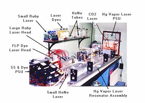
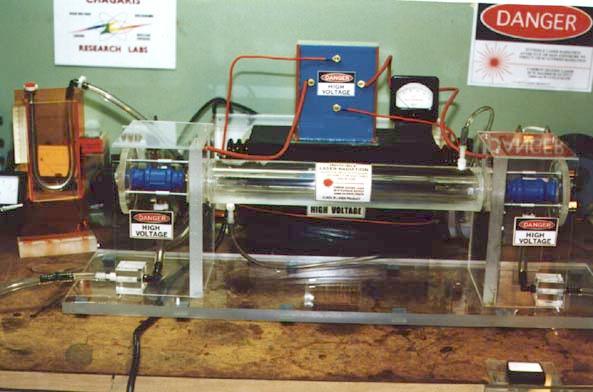
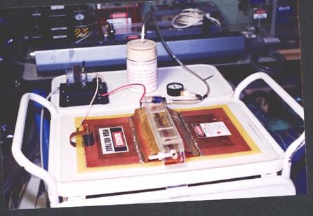
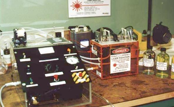
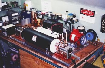
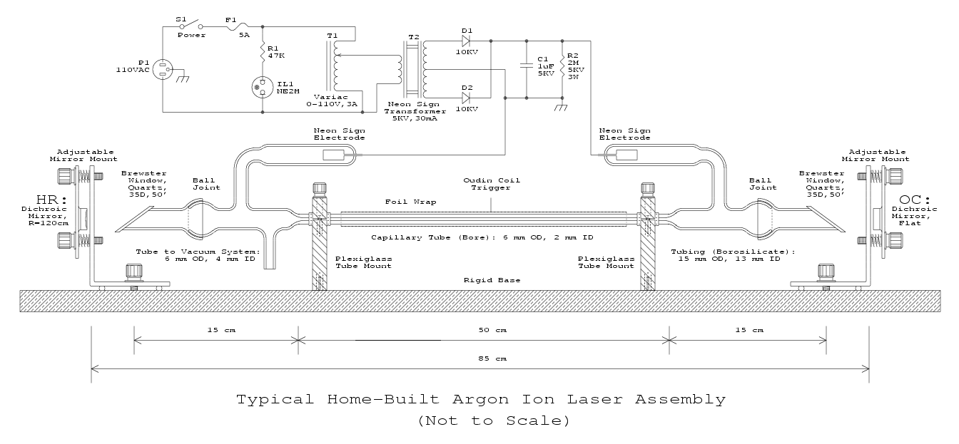
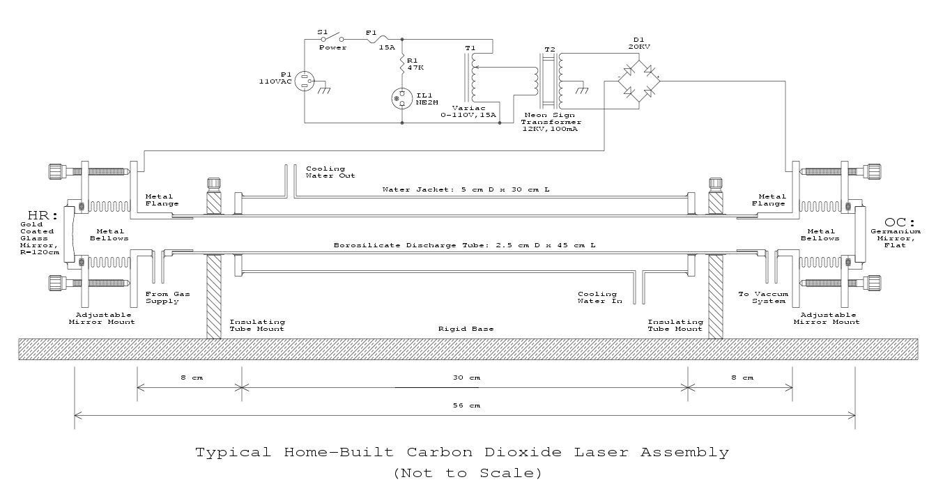
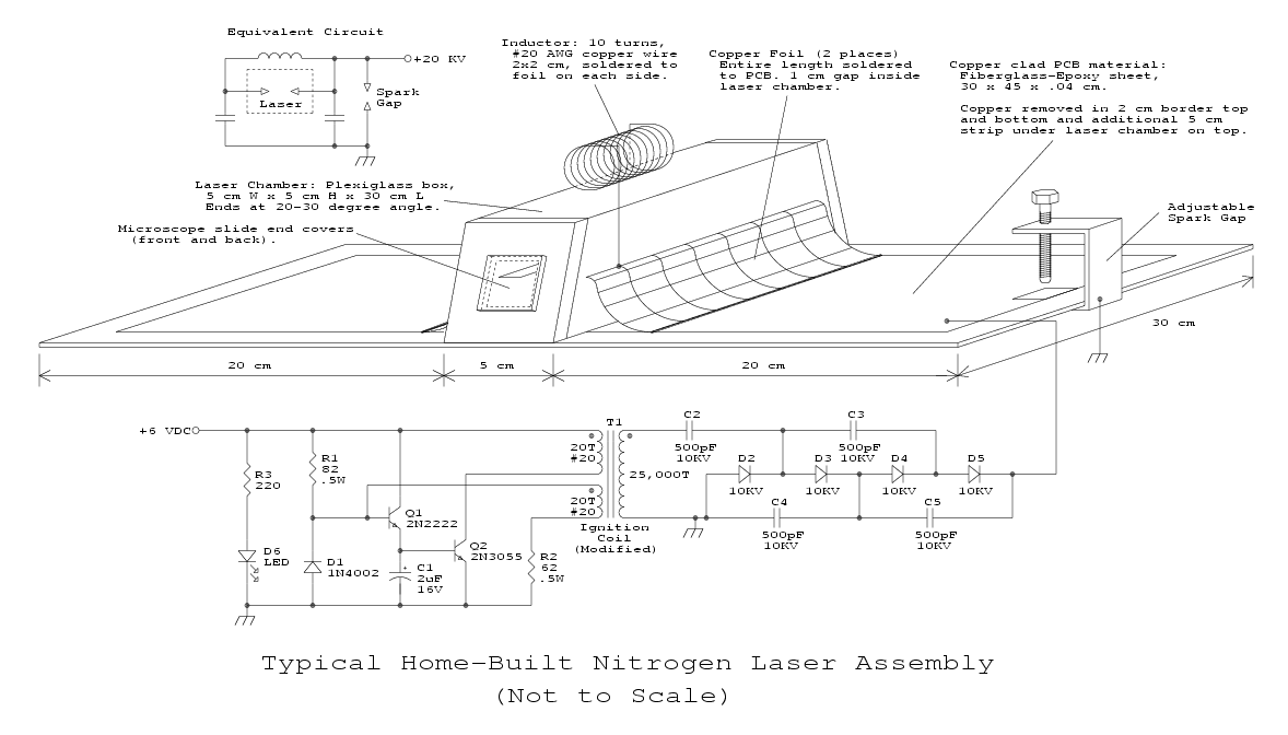
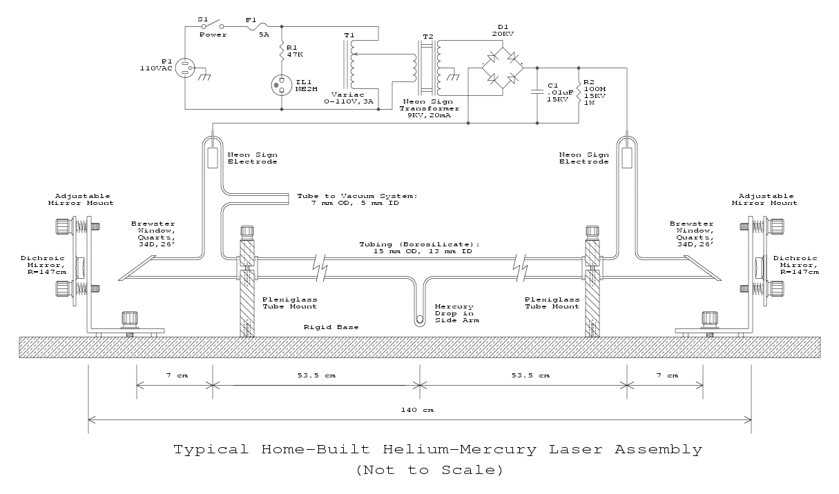
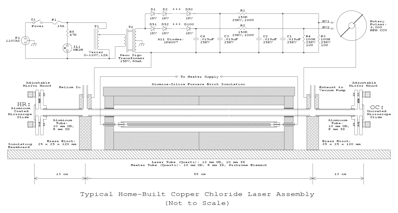
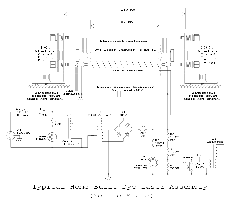
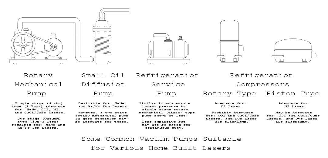
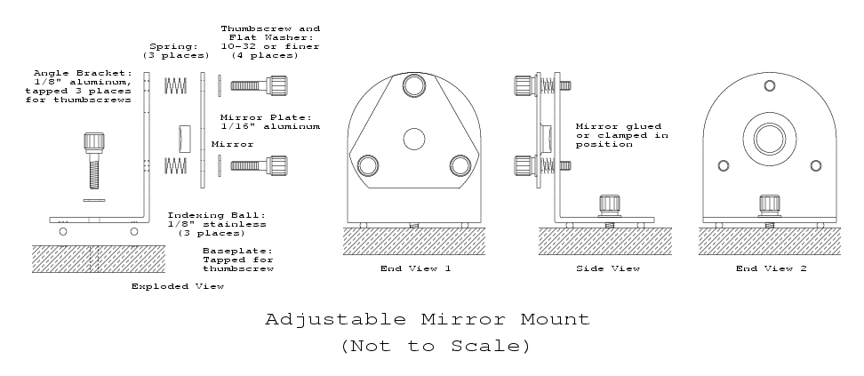